| Supply voltage | 100 to 240 VAC, 50/60 Hz
24 VAC, 50/60 Hz; 24 VDC |
|
|---|---|---|
| Operating voltage range | 85% to 110% of rated supply voltage | |
| Power consumption | 100 to 240 VAC: 5 VA
24 VAC: 3 VA, 24 VDC: 2 W |
|
| Sensor input | Thermocouple: K, J, L
Platinum resistance thermometer: Pt100, JPt100 Thermistor: E52-THE[][] Universal-input (thermocouple/platinum resistance thermometer): K, J, L, T, U, N, R, Pt100, JPt100 |
|
| Control
output |
Relay output | SPDT, 250 VAC, 3 A (resistive load) |
| Voltage output
(for driving the SSR) |
12 VDC, 21 mA (with short-circuit protection circuit) | |
| Control method | ON/OFF or 2-PID (with automatic PID parameter setting function) | |
| Alarm output | SPST-NO, 250 VAC, 1A (resistive load) | |
| Setting method | Digital setting using front panel keys | |
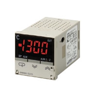
| Indication method | 7-segment digital display (character height: 13.5 mm) and deviation indicators | |
| Other functions | Setting change prohibit (key protection)
Input shift Temperature unit change (°C/°F) Direct/reverse operation Temperature range, Sensor switching (K/J/L, Pt100/JPt100) Switching is performed between a thermocouple and platinum resistance thermometer for universal-input models. Control period switching 8-mode alarm output Sensor error detection (excluding thermistor models) |
|
| Ambient operating temperature | -10 to 55°C (with no condensation or icing); with 3-year guarantee: -10 to 50°C | |
| Ambient operating humidity | 25% to 85% | |
| Storage temperature | -25 to 65°C (with no condensation or icing) | |


