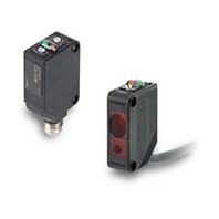
![]()
Global
These are navigation links to move inside this page.
Laser Photoelectric Sensor with Built-in Amplifier
![]()
Quick links to 'E3Z-LT / LR / LL' page in your country / territory.
Please contact our European headquarters.
Get more support via Products links, such as manuals and CAD files.
Product Search
Note: Only items related to the Catalogue are suggested.
Sensors
| Sensing method | Appearance | Connection method | Response time | Sensing distance (Red light) | Model | |
| NPN output | PNP output | |||||
| Through-beam (Emitter + Receiver) *4 | ![]() | Pre-wired (2 m) *3 | 1 ms | 60 m | E3Z-LT61 2M | E3Z-LT81 2M |
| Connector (M8, 4 pins) | E3Z-LT66 | E3Z-LT86 | ||||
| Retro-reflective with MSR function | ![]() | Pre-wired (2 m) *3 | *2 15 m (300 mm) (Using E39-R1) 7 m (200 mm) (Using E39-R12) 7 m (200 mm) (Using E39-R6) | E3Z-LR61 2M | E3Z-LR81 2M | |
| Connector (M8, 4 pins) | E3Z-LR66 | E3Z-LR86 | ||||
| Distance- settable (BGS Models) | ![]() | Pre-wired (2 m) *3 | 20 to 40 mm (Min. distance set) 20 to 300 mm (Max. distance set) | E3Z-LL61 2M | E3Z-LL81 2M | |
| Connector (M8, 4 pins) | E3Z-LL66 | E3Z-LL86 | ||||
| Pre-wired (2 m) *3 | 0.5 ms | 25 to 40 mm (Min. distance set) 25 to 300 mm (Max. distance set) | E3Z-LL63 2M | E3Z-LL83 2M | ||
| Connector (M8, 4 pins) | E3Z-LL68 | E3Z-LL88 | ||||
*1.The Reflector is sold separately. Select the Reflector model most suited to the application.
*2.Values in parentheses indicate the minimum required distance between the Sensor and Reflector.
*3.Pre-wired Models with a 0.5-m cable are also available for these products. When ordering, specify the cable length by adding “0.5M” to the end of the model number (e.g., E3Z-LT61 0.5M).
M12 Pre-wired Connector Models are also available. When ordering, add “-M1J” to the end of the model number (e.g., E3Z-LT61-M1J). The cable is 0.3 m long.
Also, the following connection forms can be manufactured. Ask your OMRON representative for details.
Pre-wired Models with 1-m or 5-m cables
Pre-wired Connector Models with M8 4-pin connectors or M8 3-pin connectors.
*4.The model number of the Emitter is expressed by adding an "L" to the set model number in the table. Example: E3Z-LT61-L 2M
The model number of the receiver is expressed by adding a "D" to the set model number in the table. Example: E3Z-LT61-D 2M
Orders for individual Emitters and Receivers are accepted. (Modifications are required for some models.)
Accessories
Slits (for E3Z-LT[][])
| Slit width | Sensing distance | Minimum detectable object (typical) | Model | Contents |
| 0.5 mm dia. | 3 m | 0.1 mm dia. | E39-S65A | One set (contains Slits for both the Emitter and Receiver) |
Reflectors (for E3Z-LR[][])
| Name | Sensing distance (typical) | Model | Remarks |
| Reflector | 15 m (300 mm) | E39-R1 | Retro-reflective models are not provided with Reflectors. Separate the Sensor and the Reflector by at least the distance given in parentheses. The MSR function is enabled. |
| 7 m (200 mm) | E39-R12 | ||
| 7 m (200 mm) | E39-R6 |
Mounting Brackets
| Appearance | Model | Quantity | Remarks |
![]() | E39-L153 | 1 | Mounting Brackets |
![]() | E39-L104 | 1 | |
![]() | E39-L43 | 1 | Horizontal Mounting Bracket * |
![]() | E39-L142 | 1 | Horizontal Protective Cover Bracket * |
![]() | E39-L44 | 1 | Rear Mounting Bracket |
![]() | E39-L98 | 1 | Metal Protective Cover Bracket * |
![]() | E39-L150 | 1 set | (Sensor adjuster) Easily mounted to the aluminum frame rails of conveyors and easily adjusted. For left to right adjustment |
![]() | E39-L151 | 1 set | |
![]() | E39-L144 | 1 | Compact Protective Cover Bracket (For E3Z only) * |
Note:When using Through-beam models, order one bracket for the Receiver and one for the Emitter.
*Cannot be used for Standard Connector models.
Sensor I/O Connectors
| Size | Cable | Appearance | Cable type | Model | |
| M8 | Standard | ![]() | 2 m | 4-wire | XS3F-M421-402-A |
| 5 m | XS3F-M421-405-A | ||||
![]() | 2 m | XS3F-M422-402-A | |||
| 5 m | XS3F-M422-405-A | ||||
| M12 (For -M1J models) | ![]() | 2 m | 3-wire | XS2F-D421-DC0-A | |
| 5 m | XS2F-D421-GC0-A | ||||
![]() | 2 m | XS2F-D422-DC0-A | |||
| 5 m | XS2F-D422-GC0-A | ||||
Note:When using Through-beam models, order one connector for the Receiver and one for the Emitter.