| Model | ZX-GT28S11 | ZX-GT2840S11 | ZX-GT28S41 | ZX-GT2840S41 |
|---|---|---|---|---|
| Output type | NPN | PNP | ||
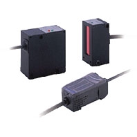
| Appearance | Separate type | Integrated type | Separate type | Integrated type |
| Light source | Visible semiconductor laser diode (wavelength 650 nm) | |||
| Laser class | Class 1 (JIS, IEC/EN, GB/T)
Class II (FDA) |
|||
| Measuring width | 28 mm | |||
| Sensing distance | 0 to 500 mm | 40 mm | 0 to 500 mm | 40 mm |
| Minimum sensing object | 0.5 mm dia. *1 | 0.2 mm dia. | 0.5 mm dia. *1 | 0.2 mm dia. |
| Linearity | ±0.1%F.S. *2 | |||
| Resolution | 10 μm (number of process values to average: 16) *3 | |||
| Temperature
characteristic |
0.01%F.S/°C *4 | |||
| Indicators (emitter) | Laser ON indicator (green), laser alarm indicator (red) | |||
| Indicators (receiver) | Optical axis setting indicator (green) | |||
| Laser OFF input/sync
input |
ON: Short-circuited with 0 V or 1.5 V max.
OFF: Open (leakage current: 0.1 mA max.) |
ON: Short-circuited with power supply
voltage or power supply voltage -1.5 V max. OFF: Open (leakage current: 0.1 mA max.) |
||
| Laser deterioration
alarm output |
NPN open-collector output
30 VDC 20 mA max. Residual voltage 1.2 V max. |
PNP open-collector output
30 VDC 20 mA max. Residual voltage 2 V max. |
||
| Power consumption
(emitter) |
30 mA max. | |||
| Power supply voltage
(emitter) |
24 VDC +10%, -15% ripple (p-p) 10% max. | |||
| Dielectric strength | 1,000 VAC, 50/60 Hz for 1 min | |||
| Insulation resistance | 20 MΩ (at 500 VDC) | |||
| Operating ambient
illumination (emitter) |
3,000 lx (incandescent light) | |||
| Operating ambient
illumination (receiver) |
1,000 lx (incandescent light) *5 | |||
| Ambient temperature | Operating: 0 to 40°C Storage: -15 to 50°C (with no icing or condensation) | |||
| Ambient humidity | Operating and storage: 35% to 85% (with no condensation) | |||
| Vibration resistance
(durability) |
10 to 150 Hz Single-amplitude: 0.75 mm for 80 min each in X, Y and Z directions | |||
| Shock resistance
(durability) |
300 m/s2 3 times each in six directions (up/down, left/right, forward/backward) | |||
| Degree of protection | IEC60529 IP40 | |||
| Cable length | 2 m | |||
| Material | Case: aluminum die-cast, Lens: glass | |||
| Weight (packed state) | Approx. 550 g | Approx. 570 g | Approx. 550 g | Approx. 570 g |
| Accessories | Laser warning labels, Instruction Sheet | |||