| Model | Standard Models | Constant-current Models | ||
|---|---|---|---|---|
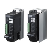
| G3PW-A2[][]EU-[] | G3PW-A2[][]EC-[]-FLK | |||
| Control method | Analog input: Phase control or optimum cycle control
Voltage ON/OFF input: ON/OFF control |
|||
| Maximum load capacity | Phase control: Linear (resistive) load, transformer primary-side control (flux
density: 1.25 T max.) Optimum cycle control: Linear (resistive) load (Transformer primaryside control is not supported.) |
|||
| Output
mode |
Analog
input |
Phase
control |
Proportional to phase angle,
proportional to square voltage, proportional to voltage |
Proportional to phase angle, proportional to
square voltage, proportional to voltage, constant-current control |
| Optimum
cycle control |
Optimum cycle control (Output is switched to 100% or 0% each half cycle.) | |||
| Voltage
ON/OFF input |
ON/OFF
control |
Proportional to voltage control | ||
| Phase | Single | |||
| Rated voltage | 100 to 240 VAC | |||
| Operating voltage range | - 15% to +10% | |||
| Power supply frequency | 50/60 Hz | |||
| Power supply frequency
fluctuation |
± 3 Hz | |||
| Power consumption | 5 VA max. (Control power (4)-(5)) | |||
| Load
current |
-A220E[] | 1 to 20 A | ||
| -A245E[] | 1 to 45 A | |||
| -A260E[] | 1 to 60 A | |||
| Inrush
current resistance |
-A220E[] | 220 A (60 Hz, 1 cycle) | ||
| -A245E[] | 440 A (60 Hz, 1 cycle) | |||
| -A260E[] | 440 A (60 Hz, 1 cycle) | |||
| I2t | -A220E[] | 400A2s (1 cycle) | ||
| -A245E[] | 1,600A2s (1 cycle) | |||
| -A260E[] | 1,600A2s (1 cycle) | |||
| Output voltage adjustable range | 0% to 98% | |||
| Input
signal for control |
Analog input | 4 to 20 mA DC (input impedance: 100 Ω) or 1 to 5 VDC (input impedance: 30.1 kΩ) | ||
| Voltage ON/OFF Input | 5 VDC (input impedance: 30.1 kΩ ) | |||
| External main setting | Specified Variable Resistor: G32X-V2K (2 kΩ, 2 W) | |||
| External duty setting | Specified Variable Resistor: G32X-V2K (2 kΩ, 2 W) | |||
| Output
value setting range |
Main setting | 0.0% to 100% | ||
| Base-up value | 0.0% to 100% (Default: 0.0%) | |||
| Upper/lower limits | Output upper limit: 0.0% to 100% (Default: 100%)
Output lower limit: 0.0% to 100% (Default: 0.0%) |
|||
| Duty setting | Duty setting = Internal duty setting x External duty setting
Internal duty setting range (set using front-panel keys or communications): 0% to 100% (Default: 100%) External duty setting range (set using external variable resistor): 0% to 100% (Default: 100%) |
|||
| Soft-start up time and
soft-start down time |
0.0 to 99.9 s (Default: 0.5 s)
Either phase control or optimum cycle control can be used. |
|||
| Constant current | --- | Current fluctuation: ± 2% FS | ||
| Load current upper limit | --- | 0.0 to 66.0 A (Default: 0.0 = OFF)
Overcurrent detection time: 500 ms max. |
||
| Current
detection |
Current
transformer (CT) |
--- | Built-in | |
| Current detection
accuracy |
--- | 10% FS of rated current | ||
| Minimum detected
load current |
--- | 1 A | ||
| Heater
burnout alarm |
Detection method | --- | According to heater resistance (with heater
resistance teaching and Heater Burnout Threshold parameter) Note: The accuracy of heater burnout detection will be lower for heaters for which the resistance significantly changes depending on the temperature. |
|
| Setting range for
heater burnout detection |
--- | 1% to 100% (Default: 100%) | ||
| Burnout detection
accuracy |
--- | 10% FS at rated current
(Not applicable to loads with variable resistance.) |
||
| Burnout detection
output lower limit |
--- | Detects a burnout at or above the specified
output value. 0.0% to 100% (Default: 0.0%) |
||
| Number of alarms
for heater burnout detection |
--- | 0 to 999 (Default: 150) | ||
| Multiple heater
burnout detections |
--- | Burnout of 1 of 10 heater elements can be
detected (at the rated current). |
||
| Event
inputs |
Number of event
inputs |
2 event inputs
Event input 1: The function of the event input can be changed with a parameter setting in the initial setting level. The event input can be used for one of the following functions. Switching the main setting between automatic and manual operation. Switching between phase control and optimum cycle control. Event input 2: Alarm reset |
||
| Contact input
conditions |
ON: 1 kΩ max., OFF: 100 kΩ min. | |||
| Non-contact input
conditions |
ON residual voltage: 1.0 V max., OFF leakage current: 0.1 mA max. | |||
| Current flow | Approx. 1.1 mA (per input) | |||
| Output voltage | 5 VDC | |||
| Alarm
outputs |
Number of alarm
outputs |
2 alarm outputs
Alarm output 1: ALARM1 (Operation stop) Alarm output 2: ALARM2 (Continue operation) Open-collector outputs (Individual common) |
||
| Maximum operating
voltage |
30 VDC | |||
| Maximum load
current |
50 mA | |||
| Maximum residual
voltage |
1.5 V | |||
| Maximum leakage
current |
0.4 mA | |||
| Serial communications | --- | One RS-485 port: CompoWay/F slave function
(See note.) Note: Connection is possible to a Basic Unit in an EJ1 Modular Temperature Controller. Parameters can be set and monitored from the CX-Thermo Support Software running on a computer that is connected to the EJ1 End Unit. |
||
| Overcurrent detection | --- | Rated current × 120% min., within 250 cycles | ||
| SSR failure detection | An error is detected within 3 seconds after an SSR failure.
Phase angle range for SSR short-circuit failure detection: 0% to 72% Phase angle range for SSR open failure detection: 28% to 100% |
|||
| Output ON voltage drop | 1.6 Vrms (at 100 % output on) | |||
| Power supply frequency error | Not within 47 to 63 Hz | |||
| Leakage current | 10 mA max. (100/110 VAC), 20 mA max. (200/220 VAC) | |||
| Insulation resistance | 100 MΩ min. (at 500 VDC) | |||
| Dielectric strength | 2,500 VAC at 50/60 Hz for 1 min between charged parts and noncharged parts | |||
| Vibration resistance | 10 to 55 to 10 Hz, 100 m/s2 | |||
| Shock resistance | 300 m/s2 | |||
| Ambient operating temperature | -15°C to 55°C (with no icing or condensation) | |||
| Ambient operating humidity | 5% to 95% | |||
| Storage temperature | -25°C to 65°C (with no icing or condensation) | |||
| Weight | G3PW-A220E[]-[]-[][][]: 1.0 kg max.
G3PW-A245E[]-[]-[][][]: 1.9 kg max. G3PW-A260E[]-[]-[][][]: 1.9 kg max. |
|||
| Applicable
Standards |
Safety Standards
(pending) |
cULus (File No.E64562)
TÜV (File No.R50140135, EN60947-4-3) |
||
| EMC Directives
(pending) |
EMI
EN60947-1 EN60947-4-3 EMS EN60947-1 EN60947-4-3 |
|||