| Model | A7D | A7DP | ||||
|---|---|---|---|---|---|---|
|
Classification
(See note 1.) |
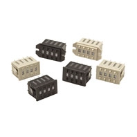
Screw mounting (back mounting)

|
Snap-in (front mounting)

|
Snap-in (front mounting)

|
|||
| Output code number | PCB terminals | |||||
| Light gray | Black | Light gray | Black | Light gray | Black | |
| 06 (binary coded decimal) | A7D-106 | A7D-106-1 | A7D-206 | A7D-206-1 | A7DP-206 | A7DP-206-1 |