| Model | A7PS | A7PH | ||
|---|---|---|---|---|
|
Classification
(See note 1.) |
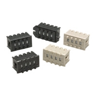
Snap-in (front mounting)

|
Snap-in (front mounting)
Long-life type 
|
||
| Character height | Decimal: 6.8 mm Hexadecimal: 4.0 mm | |||
| Terminals | Solder terminals | |||
| Color | Light gray | Black | Light gray | Black |
| Output code number | Model | |||
| 03 (decimal code) | A7PS-203 | A7PS-203-1 | A7PH-203 | A7PH-203-1 |
| 06 (binary coded decimal) | A7PS-206 | A7PS-206-1 | A7PH-206 | A7PH-206-1 |
|
07 (binary coded decimal,
with component-adding provision) * 1 |
A7PS-207 | A7PS-207-1 | A7PH-207 | A7PH-207-1 |
|
19 (decimal code,
with component-adding provision) |
A7PS-219 | A7PS-219-1 | --- | --- |
| 54 (binary coded hexadecimal) | A7PS-254 | A7PS-254-1 | A7PH-254 | A7PH-254-1 |
|
55 (binary coded hexadecimal,
with component adding provision) * 1 |
A7PS-255 | A7PS-255-1 | --- | --- |