| Appearance | Beam Gap between Muting
Trigger Beams |
output | Number of Beams | Model |
|---|---|---|---|---|
 |
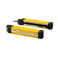
100 mm | PNP output | 8 | F3W-MA0100P |
| 300 mm | 20 | F3W-MA0300P |
Smart Muting Actuator

Select the indicator status to see the error cause and solution.
Related Contents
last update: December 9, 2021
| Appearance | Beam Gap between Muting
Trigger Beams |
output | Number of Beams | Model |
|---|---|---|---|---|
|
100 mm | PNP output | 8 | F3W-MA0100P |
| 300 mm | 20 | F3W-MA0300P |
Note: Use with the PNP output model safety light curtain.
| Appearance | Type | Cable
length |
Specifications | Model |
|---|---|---|---|---|
 |
M12 connector
(5-pin), 5 wires Color: Gray |
3 m |  |
F39-JG3A-L |
| 7 m | F39-JG7A-L | |||
| 10 m | F39-JG10A-L | |||
| 15 m | F39-JG15A-L | |||
| 20 m | F39-JG20A-L | |||
| For receiver
M12 connector (8-pin), 8 wires Color: Black |
3 m |  |
F39-JG3A-D | |
| 7 m | F39-JG7A-D | |||
| 10 m | F39-JG10A-D | |||
| 15 m | F39-JG15A-D | |||
| 20 m | F39-JG20A-D |
* A set of two Single-Ended Cables (one for emitter and one for receiver) is also available.
Model: Model number without the -L/-D at the end (F39-JG[]A)
| Appearance | Type | Cable
length |
Specifications | Model |
|---|---|---|---|---|
 |
M12 connector
(5-pin) on both ends Color: Gray |
0.5 m |  |
F39-JGR5B-L |
| 1 m | F39-JG1B-L | |||
| 3 m | F39-JG3B-L | |||
| 5 m | F39-JG5B-L | |||
| 7 m | F39-JG7B-L | |||
| 10 m | F39-JG10B-L | |||
| 15 m | F39-JG15B-L | |||
| 20 m | F39-JG20B-L | |||
| M12 connector
(8-pin) on both ends Color: Black |
0.5 m |  |
F39-JGR5B-D | |
| 1 m | F39-JG1B-D | |||
| 3 m | F39-JG3B-D | |||
| 5 m | F39-JG5B-D | |||
| 7 m | F39-JG7B-D | |||
| 10 m | F39-JG10B-D | |||
| 15 m | F39-JG15B-D | |||
| 20 m | F39-JG20B-D |
* A set of two Double-Ended Cables (one for emitter and one for receiver) is also available.
Model: Model number without the -L/-D at the end (F39-JG[]B)
| Appearance | Type | Specifications | Model |
|---|---|---|---|

|
For emitter
M12 connectors. Used for reduced wiring. |

|
F39-GCN4-L |

|
For receiver
(PNP output) M12 connectors. Used for reduced wiring. |

|
F39-GCN4-D |

|
Includes one
each of F39-GCN4-L and F39-GCN4-D |
- | F39-GCN4 |

|
Water-resistive
Cover for 4-Joint Plug/Socket Connector |
One water-resistive cover for an F39-GCN4-L/-D
4-Joint Plug/Socket Connector. You can use this when the MA2 connector part is not used. Material: PBT. IP67 rated when attached. Smartclick mechanism. |
XS5Z-11 |

|
Dust Cover for
4-Joint Plug/Socket Connector |
One dust cover for an F39-GCN4-L/-D 4-Joint Plug/
Socket Connector. You can use this when the MA2 connector part is not used. Material: Rubber/black. This cover does not ensure IP67 degree of protection. XS2Z-14: Attach to a pin block inside the M12 female screw. XS2Z-15: Attach to a M12 female screw. When attaching the cover to the connector, press the cover onto the connector until the connector is fully inserted into the cover. |
XS2Z-14 |

|
XS2Z-15 |
| Appearance | Specification | Application | Remarks | Model |
|---|---|---|---|---|
 |
Standard Fixed
Bracket |
Bracket to mount the F3W-MA.
Side mounting and backside mounting possible. |
Two brackets
per set |
F39-LGF |
 |
Standard
Adjustable Bracket |
Bracket to mount the F3W-MA.
Beam alignment after mounting possible.The angle adjustment range is ±15°. Side mounting and backside mounting possible. |
Two brackets
per set |
F39-LGA |
 |
F3W-MA
Bracket |
Bracket to fix the F3W-MA to the F3SG-RA.
F39-LGMAL: L-shaped configuration F39-LGMAT: T-shaped configuration Beam alignment after mounting possible. When using the F3W-MA Bracket, it is necessary to add an extra Standard Adjustable Bracket (F39-LGA) to the F3SG-RA. * Please also purchase Standard Adjustable Bracket (F39-LGA). |
Two brackets
per set |
F39-LGMAL |
 |
F39-LGMAT |
last update: December 9, 2021
© Copyright OMRON Corporation 2007 - 2024. All Rights Reserved.