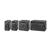
Page top

S8VK-WA

Switch Mode Power Supply (240/480/960/2000-W Models)

S8VK-WA

200 V Three-phase Input Power Supplies A solution to three-phase balance problems

Ratings, Characteristics, and Functions

Power rating 240 W 480 W 960 W
Output voltage (VDC) 24 V 24 V 24 V
Efficiency *1 Three-phase
200 VAC input
93% typ. 94% typ. 95% typ.
Single-phase/
two-phase
200 VAC input
92% typ. 93% typ. 94% typ.
Three-phase
230 VAC input
93% typ. 94% typ. 95% typ.
Single-phase/
two-phase
230 VAC input
93% typ. 94% typ. 95% typ.
Input con-
ditions
Input voltage range *2 Three-phase/single-phase/two-phase
170 to 264 VAC, 265 to 300 VAC (1 second)
240 to 350 VDC
Frequency *2 50/60 Hz (47 to 63 Hz)
Input current
*1
Three-phase
200 VAC input
0.80 A typ. 1.6 A typ. 3.1 A typ.
Single-phase/
two-phase
200 VAC input
1.4 A typ. 2.6 A typ. 5.2 A typ.
Three-phase
230 VAC input
0.70 A typ. 1.4 A typ. 2.7 A typ.
Single-phase/
two-phase
230 VAC input
1.2 A typ. 2.3 A typ. 4.5 A typ.
Power factor *1 0.9 min.
Leakage
current *3
Three-phase
200 VAC input
1 mA max.
Three-phase
230 VAC input
1 mA max.
Inrush
current *4
(for a cold
start at 25°C)
Three-phase
200 VAC input
13 A typ. 13 A typ. 14 A typ.
Three-phase
230 VAC input
15 A typ. 15 A typ. 16 A typ.
Output
character-
istics
Rated output current 10 A 20 A 40 A
Power Boost Function 15 A 30 A 60 A
Voltage adjustment range *5 24 to 29.5 V (with V.ADJ) 24 to 28 V (with V.ADJ)
Ripple noise
voltage *6
Three-phase
200 to 240
VAC input
50 mVp-p max.
at 20 MHz of
bandwidth
120 mVp-p max.
at 20 MHz of
bandwidth
60 mVp-p max.
at 20 MHz of
bandwidth
Input variation influence *7 0.5% max.
Load variation influence *8 1.5% max.
Temperature
variation
influence
200 to 240
VAC input
0.05%/°C max.
Startup
time *9
Three-phase
200 VAC input
1,000 ms max.
Three-phase
230 VAC input
1,000 ms max.
Output hold
time *9
Three-phase
200 VAC input
35 ms typ. 30 ms typ. 25 ms typ.
Three-phase
230 VAC input
35 ms typ. 30 ms typ. 25 ms typ.
Additional
functions
Overload protection Yes, automatic reset, intermittent operation type
Refer to Overload Protection below.
Overload protection for
terminals
No
Overvoltage protection Yes, 130% or higher of rated output voltage, power shut off (shut off
the input voltage and turn on the input again),
Refer to Overvoltage Protection below.
Series operation Yes (For up to two Power Supplies; external diodes required.)
Parallel operation Yes (For up to two Power Supplies), Refer to Parallel Operation on
Data sheet.
INPUT OK Indicator Yes (LED: Green)
DC OK Indicator Yes (LED: Green)
Iout > 100% Indicator Yes (LED: Yellow)
DC OK Signal Output Yes (MOS FET relay output 30 VDC max., 50 mA max.)
Iout > 100% signal output Yes (MOS FET relay output 30 VDC max., 50 mA max.)
Insulation Withstand voltage 3.0 kVAC for 1 min. (between all input terminals and all output terminals,
signal output terminals), cutoff current 20 mA
2.0 kVAC for 1 min. (between all input terminals and PE terminals),
cutoff current 20 mA
1.0 kVAC for 1 min. (between all output terminals, signal output terminals
and PE terminals), cutoff current 25 mA (240 W/480 W/960 W)
1.0 kVAC for 1 min. (between all output terminals, signal output terminals
and PE terminals), cutoff current 40 mA (2000 W)
0.5 kVAC for 1 min. (between all output terminals and all signal output
terminals), cutoff current 10 mA
Insulation resistance 100 MΩ min. (between all output terminals, signal output terminals
and all input terminals / PE terminals) at 500 VDC
Environ-
ment
Ambient operating
temperature *10
-40 to 70°C (Derating is required according to the temperature.
Refer to Engineering Data on Data sheet.) (with no condensation or
icing)
Storage temperature -40 to 85°C (with no condensation or icing)
Ambient operating humidity 95% max. (Storage humidity: 95% max.)
Vibration resistance *11 10 to 55 Hz, maximum 5 G, 0.42 mm single amplitude for 2 h each in
X, Y, and Z directions
Shock resistance *11 294 m/s2, 3 times each in ±X, ±Y, ±Z directions
Reliability MTBF *12 290,000 hrs typ. 230,000 hrs typ. 170,000 hrs typ
Expected life *13 10 years min.
Construc-
tion
Weight 800 g max. 1,050 g max. 1,750 g max.
Cooling fan No
Degree of protection IP20 by EN/IEC 60529
Standards Harmonic current emissions Conforms to EN 61000-3-2 (single-phase, two-phase *14)
Complies with JIS C 61000-3-2 (single-phase, two-phase, three-phase)
EMI Conducted
emissions
Conforms to EN 61204-3 Class B,
EN 55011 Class B (three-phase)
Conforms to EN 61204-3 Class A,
EN 55011 Class A (single-phase,
two-phase)
Conforms to EN 61204-3 Class B,
EN 55011 Class (three-phase)
Conforms to EN 61204-3 Class B,
EN 55011 Class (single-phase,
two-phase *16)
Conforms to EN 61204-3 Class
EN 55011 Class A (single-phase,
two-phase)
Radiated
emissions
EMS Conforms to EN 61204-3 high severity levels
Safety standards • UL 508 (Listing)
• CSA C22.2 No.107.1 (cUL)
• UL 62368-1 (Recognition) OVC II (≤ 3000 m) Pol2
• CSA C22.2 No.62368-1 (cUR) OVC II (≤ 3000 m) Pol2
• EN/IEC 62477-1 OVC III (≤ 2000 m) OVC II (2000 m < and ≤
3000 m) Pol2
• EN/IEC 62368-1 OVC II (≤ 3000 m) Pol2
• RCM (EN61000-6-4)
• Complies with PELV (EN/IEC 60204-1)
• Complies with EN/IEC 61558-2-16
SEMI Complies with SEMI F47-0706 (three-phase / single-phase / two-phase
200 to 240 VAC input)

Power rating 2000 W
Output voltage (VDC) 24 V 48 V
Efficiency *1 Three-phase
200 VAC input
95% typ. 96% typ.
Single-phase/
two-phase
200 VAC input
95% typ. 95% typ.
Three-phase
230 VAC input
96% typ. 96% typ.
Single-phase/
two-phase
230 VAC input
95% typ. 96% typ.
Input con-
ditions
Input voltage range *2 Three-phase/single-phase/two-phase
170 to 264 VAC, 265 to 300 VAC (1 second)
240 to 384 VDC
Frequency *2 50/60 Hz (47 to 63 Hz)
Input current
*1
Three-phase
200 VAC input
6.5 A typ. 6.9 A typ.
Single-phase/
two-phase
200 VAC input
11 A typ. 12 A typ.
Three-phase
230 VAC input
5.7 A typ. 6.0 A typ.
Single-phase/
two-phase
230 VAC input
9.5 A typ. 10 A typ.
Power factor *1 0.9 min.
Leakage
current *3
Three-phase
200 VAC input
3.5 mA max. 3.5 mA max.
Three-phase
230 VAC input
3.5 mA max. 3.5 mA max.
Inrush
current *4
(for a cold
start at 25°C)
Three-phase
200 VAC input
18 A typ. 22 A typ.
Three-phase
230 VAC input
16 A typ. 16 A typ.
Output
character-
istics
Rated output current 85 A 45 A
Power Boost Function 127.5 A 67.5 A
Voltage adjustment range *5 24 to 28 V (with V.ADJ) 48 to 56 V (with V.ADJ)
Ripple noise
voltage *6
Three-phase
200 to 240
VAC input
170 mVp-p max. at 20 MHz of
bandwidth
190 mVp-p max. at 20 MHz of
bandwidth
Input variation influence *7 0.5% max.
Load variation influence *8 1.5% max.
Temperature
variation
influence
200 to 240
VAC input
0.05%/°C max.
Startup
time *9
Three-phase
200 VAC input
1,000 ms max.
Three-phase
230 VAC input
1,000 ms max.
Output hold
time *9
Three-phase
200 VAC input
25 ms typ. 25 ms typ.
Three-phase
230 VAC input
25 ms typ. 25 ms typ.
Additional
functions
Overload protection Yes, inverted L voltage drop, automatic reset, power cut off if higher of
rated output current continues and turn on the input again.
Refer to the Overload Protection below.
Overload protection for
terminals
Yes, inverted L voltage drop,
automatic reset, power cut off if
overprotection (terminal blocks)
continues and turn on the input
again.
Refer to the Overload Protection
below.
No
Overvoltage protection Yes, 130% or higher of rated output voltage, power shut off (shut off
the input voltage and turn on the input again),
Refer to Overvoltage Protection below.
Series operation Yes (For up to two Power Supplies; external diodes required.)
Parallel operation Yes (For up to two Power Supplies), Refer to Parallel Operation on Data
sheet.
Use with the switch for parallel operation set to the “PARALLEL” side
(the rated output current limited to 80%).
INPUT OK Indicator Yes (LED: Green)
DC OK Indicator Yes (LED: Green)
Iout > 100% Indicator Yes (LED: Yellow)
DC OK Signal Output Yes (MOS FET relay output 30 VDC max., 50 mA max.)
Iout > 100% signal output Yes (MOS FET relay output 30 VDC max., 50 mA max.)
Insulation Withstand voltage 3.0 kVAC for 1 min. (between all input terminals and all output terminals,
signal output terminals), cutoff current 20 mA
2.0 kVAC for 1 min. (between all input terminals and PE terminals),
cutoff current 20 mA
1.0 kVAC for 1 min. (between all output terminals, signal output terminals
and PE terminals), cutoff current 25 mA (240 W/480 W/960 W)
1.0 kVAC for 1 min. (between all output terminals, signal output terminals
and PE terminals), cutoff current 40 mA (2000 W)
0.5 kVAC for 1 min. (between all output terminals and all signal output
terminals), cutoff current 10 mA
Insulation resistance 100 MΩ min. (between all output terminals, signal output terminals
and all input terminals / PE terminals) at 500 VDC
Environ-
ment
Ambient operating
temperature *10
-40 to 70°C (Derating is required according to the temperature.
Refer to Engineering Data on Data sheet.) (with no condensation or
icing)
Storage temperature -40 to 85°C (with no condensation or icing)
Ambient operating humidity 95% max. (Storage humidity: 95% max.)
Vibration resistance *11 10 to 55 Hz, maximum 5 G, 0.42 mm single amplitude for 2 h each in
X, Y, and Z directions
Shock resistance *11 147 m/s2, 3 times each in ±X, ±Y, ±Z directions
Reliability MTBF *12 90,000 hrs
Expected life *13 10 years min.
Construc-
tion
Weight 3200 g max.
Cooling fan No
Degree of protection IP20 by EN/IEC 60529
Standards Harmonic current emissions Conforms to EN 61000-3-2 (single-phase, two-phase) *14
Complies with JIS C 61000-3-2 (single-phase, two-phase, three-phase)
*15
EMI Conducted
emissions
Conforms to EN 61204-3 Class B,
EN 55011 Class B (single-phase, two-phase, three-phase)
Radiated
emissions
EMS Conforms to EN 61204-3 high severity levels
Safety standards • UL 508 (Listing)
• CSA C22.2 No.107.1 (cUL)
• UL 62368-1 (Recognition) OVC II (≤ 3000 m) Pol2
• CSA C22.2 No.62368-1 (cUR) OVC II (≤ 3000 m) Pol2
• EN/IEC 62477-1 OVC III (≤ 2000 m)
 OVC II (2000 m < and ≤ 3000 m) Pol2
• EN/IEC 62368-1 OVC II (≤ 3000 m) Pol2
• RCM (EN61000-6-4)
• Complies with PELV (EN/IEC 60204-1)
• Complies with EN/IEC 61204-7
SEMI Complies with SEMI F47-0706 (three-phase / single-phase / two-phase
200 to 240 VAC input)

*1. The value is when both rated output voltage and rated output current are satisfied.
*2. Do not use an inverter output for the product. Inverters with an output frequency of 50/60 Hz are available, but the rise
      in the internal temperature of the product may result in ignition or burning. If the input is connected to a UPS, do not
      connect a UPS with a square-wave output. Doing so will cause the internal temperature of the product to increase,
      possibly causing smoking or burning.
*3. The value is determined according to the Electrical Appliances and Material Safety Act.
*4. Values for a cold start at 25°C. Refer to Inrush Current, Startup Time, and Output Hold Time on below.
*5. If the output voltage adjuster (V. ADJ) is turned, the voltage will increase by more than the voltage adjustment range.
      When adjusting the output voltage, confirm the actual output voltage from the product and be sure that the load is not
      damaged.
*6. The value is when both rated output voltage and rated output current are satisfied. A characteristic when the ambient
     operating temperature is 25°C.
*7. This is the maximum variation in the output voltage when the input voltage is gradually changed within the allowable
     input voltage range at the rated output voltage and rated output current.
*8. 200 to 240 VAC input, in the range of 0 A to the rated output current.
*9. This is the value when both rated output voltage and rated output current are satisfied and at room temperature
      (25°C). Refer to Inrush Current, Startup Time, and Output Hold Time on below for details.
*10. At -40 to -25°C, time will be required before the rated output voltage is output after the input voltage is input.
*11. If there is a possibility that the Unit will be subject to vibration or shock, use a steel DIN Rail.
*12. MTBF is calculated according to JEITA RCR-9102.
*13. Refer to Recommended Replacement Periods and Periodic Replacement for Preventive Maintenance on Data Sheet for
       details.
*14. EN61000-3-2 does not applied to three-phase 200 to 240 VAC input models.
       When using 2000 W models, conforms to EN 61000-3-2 under the following condition.
       2000 W: At the rated output voltage, and 75% or less than the rated output current
*15. Complies with JIS C 61000-3-2 (single-phase, two-phase, three-phase) under the following condition.
       Three-phase: at the rated output voltage and 75 or less than the rated output current
       Single-phase or two-phase: at the rated output voltage and the rated output current.
*16. Class B compliance was met with the following configuration.

S8VK-WA Specifications 3

Standard Compliance

• To comply with PELV output requirements for EN/IEC 60204-1, ground the negative side of the output (-V) to a protective
   earth (PE).
• EN/IEC 61558-2-16, EN/IEC 61204-7
   When certification was received for EN/IEC 60204-1 (Machinery Safety), it was necessary to go through a control
   transformer to the control circuits. However, a control transformer is not always necessary for product that have been
   certified for the safety standard for OVCIII or for product that use a transformer that complies with EN/IEC 61558-2-16 or
   EN/IEC 61204-7.
• Safety Standards for a DC Input
   <S8VK-WA240, 380, 960>
   The following safety standards apply to a DC input: UL 62368-1, cUR (CSA C22.2 No. 62368-1), EN/IEC 62368-1,
   EN/IEC 62477-1, EN/IEC 61558-2-16
   <S8VK-WA202>
   The following safety standards apply to a DC input: UL 62368-1, cUR (CSA C22.2 No. 62368-1), EN/IEC 62368-1,
   EN/IEC 62477-1, EN/IEC 61204-7.
   Safety standard compliance is achievable by connecting a safety standard certified fuse to the (L1/+) side.
   For a DC power input, connect (L1/+) side to (+), and (L3/-) side to (-).
   To select a safety standard fuse, refer to Recommended circuit breakers and fuses on Data Sheet.

Inrush Current, Startup Time, and Output Hold Time

S8VK-WA Specifications 5

Note: Twice the normal inrush current will flow during parallel operation or for backup operation. Therefore, check the fusing
         characteristics of fuses and operating characteristics of breakers making sure that the external fuses will not burn out
         and the circuit breakers will not be activated by the inrush current.

Overload Protection

The overload protection circuit will protect the product from short-circuit currents and overcurrents.

<S8VK-WA240, 480, 960> *1 *2

When the load current reaches 151% to 175% of the rated current, the output voltage is automatically lowered. When the overload status is cleared, the output voltage is automatically recovered to the normal status.

<S8VK-WA202> (switch for parallel operation: SINGLE) *1 *2 *3

When the load current reaches 151% to 175% of the rated current, the output voltage is automatically lowered. When the overload status is cleared, the output voltage is automatically recovered to the normal status.
The output voltage is cut off under the following conditions.
• A current exceeding the rating continues for more than 5 seconds
• The overload status continues for three seconds or longer while the output voltage is lowered due to overload protection
To reset the protection, turn OFF the input power for three minutes or longer and then turn it back ON.

<S8VK-WA202> (switch for parallel operation: PARALLEL) *1 *2 *3

When the load current reaches 81% to 110% of the rated current, the output voltage is automatically lowered. When the overload status is cleared, the output voltage is automatically recovered to the normal status.
The output voltage is cut off under the following conditions.
• The overload status continues for three seconds or longer while the output voltage is lowered due to overload protection.
To reset the protection, turn OFF the input power for three minutes or longer and then turn it back ON.

S8VK-WA Specifications 10
S8VK-WA Specifications 11

*1. Internal parts may occasionally deteriorate or be damaged if a short-circuited or overload status continues during
     operation. Use the product after verifying that the Iout > 100% indicator is not lit or the Iout>100% signal output is OFF.
*2. Internal parts may possibly deteriorate or be damaged if the Power Supply is used for applications with inrush current or
     overloading at the load end. Do not use the Power Supply for such applications.
*3. Do not turn ON the power again until the cause of the overvoltage has been removed.

<Only S8VK-WA20224> (for terminal block)

If use continues for longer than 10 seconds while a current exceeds a 45 A output current for each terminal of output, overload protection is activated. The maximum current of each terminal is limited so that it will be 45 A or lower and the output voltage is also lowered.
When the overload status is cleared, the output current and the output voltage are automatically recovered to the normal status.
The output voltage is cut off when the overload status continues for three seconds or longer while the output voltage is lowered due to overload protection. To reset the protection, turn OFF the input power for three minutes or longer and then turn it back ON.

S8VK-WA Specifications 13

Note: 1. The rated current per pole of the output terminals will be 45 A.
             If a current exceeding 45 A will flow, wire using multiple poles at the same time.
         2. If overload protection is activated for even one output terminal pole, the output voltage of all terminals will be
             lowered.
         3. Make the length and thickness of the wires connected to the load the same so that the current flowing through
             them will be the same.

Overvoltage Protection

Overvoltage will be detected to prevent the load from being subjected to excessive voltage when the feedback circuit in the Power Supply fails, etc.
When an excessive voltage that is approximately 130% of the rated output voltage or more is output, the output voltage is cut OFF, preventing damage to the load due to overvoltage.
Reset the input power by turning it OFF for at least three minutes and then turning it back ON again.
Note: Do not turn ON the power again until the cause of the overvoltage has been removed.

INPUT OK Indicator

The INPUT OK indicator will light when the input voltage exceeds the lower limit value of the permissible range.
Note: The voltage may be applied even if the indicator does not light.
         Be sure to check the input voltage when performing wiring.

DC OK Indicator/Signal Output

The DC OK indicator will light when the output voltage is more than 90% of the rated output voltage, and the internal MOS FET relay is conducted (turned ON).
Note: 1. The output voltage may be generated even if the indicator does not light. Be sure to check the output voltage when
             connecting to the load.
         2. This function monitors the voltage at the power output terminals.
             To check the voltage accurately, measure the voltage at the load end.
         3. If the output voltage is set to less than 90% of the rated output voltage, the indicator may go off and the signal
            output may be turned OFF.

Iout > 100% Indicator/Signal Output

The Iout > 100% indicator lights up when the output current exceeds the rated output current, and the internal MOS FET relay is conducted (turned ON).
Note: 1. The Iout > 100% Indicator may light up, and the Iout > 100% Signal Output may turn ON during peak current
            operation, however, the Power Supply can be used as long as the operating conditions specified in Peak current
            (Data Sheet) are satisfied.
         2. Even when the operating conditions for parallel operation are satisfied, the Iout>100% Indicator / Signal Output
             may operate, so do not use the Iout>100% Indicator / Signal Output.
         3. During a short-circuit, the indicator will operate intermittently due to the overload protection function. When this
             happens, the indicator will blink in accordance with the intermittent operation, and the Iout > 100% signal output
             will repeated turn ON and OFF.
            The shortest ON time of the Iout > 100% signal output during intermittent operation is 5 ms. (Other than S8VK-
            WA202)

Specifications of the Signal Output Terminals (between DC OK Signal Output Terminal and COM Terminal, and between Iout > 100% Signal Output Terminal and COM Terminal)

Since the Signal Output is composed of the MOS FET relay, it does not have any polarity.
30 VDC max., 50 mA max.
Residual voltage when the function is ON: 2 V max.
Leakage current when the function is OFF: 0.1 mA max.
Note: 1. Internal current control circuits are not provided internally for output signals. Do not allow the output current to
             exceed 50 mA.
         2. After completing wiring, confirm that the circuits operate correctly.

Identification of error locations at the input, product, and load side by the Indicator or Signal Output, and troubleshooting for the same (Maintenance point indicator)

Error locations at the input, product, and load side can be identified by the INPUT OK, DC OK, Iout > 100% Indicator / Signal Output.

S8VK-WA Specifications 19

Time chart (Operation of the Indicator/Signal Output according to the product status)

S8VK-WA 240, 480, 960

S8VK-WA Specifications 21

S8VK-WA202

S8VK-WA Specifications 22