Question
What concepts are applied for countermeasures for noise for a Servo System?
Answer
1. Countermeasures for Noise
The following four aspects are important when considering countermeasures for noise.
1-1. Investigate Noise Sources
Devices that cause rapid changes in voltage or current are noise sources.
Generally the larger the signal power, the stronger the noise source becomes.
List the noise sources that surround your Servo System.
1-2. Identify the Noise Transmission Path
Once you know the source, position, type, and characteristic of the noise, you can narrow down the noise transmission paths. For each possible noise transmission path, apply a countermeasure. Start with the most probable path. You can narrow down the noise transmission path by seeing how effective the countermeasure is.
Another method is to use shield boards connected to frame grounds to check the effect of electromagnetic waves, electromagnetic induction, and electrostatic coupling.
1-3. Noise Countermeasures Must Not Be Removed until the End
Even if the countermeasure applied to a noise transmission path was ineffective, do not remove the countermeasure. There may be several noise transmission paths and the countermeasure that you applied may be blocking the second largest noise path.
1-4. Noise Transmission Paths That Are Common in Servo Systems
Leakage current from the motor electrostatic coupling to the frame ground becomes large in Servo Systems and Inverters.
If the current is not absorbed very well, the frame ground potential will become unstable. This increases cases where noise is transmitted to other devices through the frame ground.
2. Actual Noise Countermeasures
Countermeasures for noise transmission paths as well as countermeasures against leakage current are described below.
2-1. Countermeasures for Electrostatic Coupling
| Countermeasure | Purpose | Precautions | Wiring |
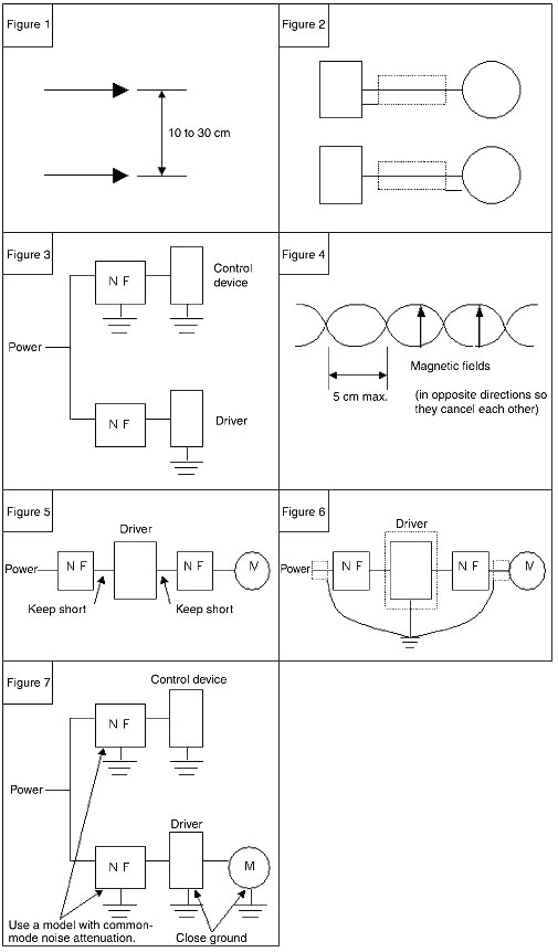
| Move the signal lines further apart. | To reduce electrostatic coupling | Move them at least 10 cm apart; 30 cm is sufficient. | Refer to Figure 1 below. |
| Use a conductive shield (e.g., storage panel, metal pipe, shield). | To reduce electrostatic coupling | The conductor to be used as a shield must be connected to the frame ground. The ground must be on one end only. (No current flow can be allowed in the shield.) | Refer to Figure 2 below. |
2-2. Countermeasures for Conductive Coupling
| Countermeasure | Purpose | Precautions | Wiring |
| Noise filter | Attenuation of high frequency components | After a noise filter is inserted, completely separate the lines to the control line and the power line. | Refer to Figure 3 below. |
2-3. Countermeasures for Electromagnetic Induction
| Countermeasure | Purpose | Precautions | Wiring |
| Move the signal lines further apart. | To reduce the magnetic field strength. | Move them at least 10 cm apart; 30 cm is sufficient. | Refer to Figure 1 below. |
| Twist the signal line and return line together. | To reduce the area affected by a magnetic field. To mutually cancel out the effect of magnetic fields. | Keep the twists small (5 cm or smaller). Do not make the twists for the power line and the signal line at the same pitch. | Refer to Figure 4 below. |
2-4. Countermeasure for Electromagnetic Waves
| Countermeasure | Purpose | Precautions | Wiring |
| Noise filter | Attenuation of high frequency components | Keep the wiring short in areas in which noise is not attenuated by a noise filter. | Refer to Figure 5 below. |
| Use a conductive shield | To reduce electrostatic coupling | The conductor to be used as a shield must be connected to the frame ground. The ground must be on one end only. (No current flow can be allowed in the shield.) | Refer to Figure 6 below. |
Note:Use a noise filter for an output without a capacitor for the noise filter on the driver output side.
2-5. Countermeasure for Leakage Current
| Countermeasure | Purpose | Precautions | Wiring |
| Noise filter | To attenuate the common-mode (between power and frame ground) high-frequency component | Use a noise filter that can remove the common-mode noise (must be implemented even if it is only for the Control device). | Refer to Figure 7 below. |
| Connect to ground with a thick line at the shortest possible distance. | To let the leakage current escape quickly, and to reduce voltage changes. | The wire diameter must be at least 2 mm2. Keep the wiring distance as short as possible. Directly ground to 100 W or less. |
3. Other Noise Countermeasures
If noise-related errors persist even after applying noise countermeasures, try the following measures. They may be effective depending on the model of Position Controller and Servo Driver.
3-1. The Positioning Point Is Offset When Connected to Position Controller with a Pulse Output
Problem:
Noise is superimposed on the command pulse input signal, so the Driver takes the noise as a command signal.
Countermeasures:
Separate the power source.
Use a dedicated power supply for the Controller's pulse output.
It is effective to separate the ground line as well.
Shield the pulse signal.
If positioning is offset even after separating the power source, connect both ends of the command pulse signal line shield (shielded twisted-pair cable) to the frame ground.
Note:
Make sure that the Controller and the Driver are always grounded to 100 Ω or less.
If the grounding is ineffective, it will make the problems worse.
3-2. The Positioning Point Is Offset When Connected to Connect to a Controller with an Analog Output
Problem:
Noise is superimposed on the feedback pulse (encoder signal), so the Controller takes the noise as a feedback pulse.
Countermeasures:
Shield the feedback pulse signal.
Connect both ends (Controller and Driver) of the feedback pulse signal shield (shielded twisted-pair shielded cable) to the frame ground.
Note:
Make sure that the Controller and the Driver are always grounded to 100 Ω or less.
If the grounding is ineffective, it will make the problems worse.
3-3. The Ground Is Bad
Problem:
If the ground to 100 Ω is bad, noise will be transmitted from ground. If noise persists no matter what countermeasures are used, check the ground potential.
Countermeasures:
Connect to a good ground at 100 Ω or less.
Improve the condition of the ground.
Separate the frame ground of high-power devices and low-power devices.
Float the frame ground line of the Control device and other applicable devices
Cut the shield of the shielded cable.
These countermeasures are for worst case scenarios. If the Servo System is operating in an environment with serious noise problems, it will not operate at full capacity.
Recommended Products
 CS1W-NC[]71
Decrease TCO with Simple Operation, Reduced Wiring, Batch Settings, and Batch Management
CJ2
Introducing the Flagship CJ2 CPU Units, with Built-in Multifunctional Ethernet Port.