Refer to the Safety Precautions for individual products for precautions specific to each product.

The following Timers contain lithium batteries that are explosion proof.

Timers with Built-in Batteries:H5S, H5F, H4KV, and H5L
The Timer contains a lithium battery, which may occasionally ignite or rupture. Do not disassemble, deform under pressure, heat to 100°C or higher, or incinerate the Timer.
Precautions for Safe Use
Operating Environment
Use the product within the ratings specified for ambient operating temperature and ambient operating humidity for each model.
Store the product with the specified temperature range for each model. If the product has been stored at a temperature of less than −10°C, allow the product to stand at room temperature for at least 3 hours before using it.
Use the product within the performance specified for water and oil exposure for each model.
Do not use the product in locations subject to shock and vibration.
Long-term usage in such locations may damage the product due to stress.
Magnetic contactors generate a shock of 1,000 to 2,000 m/s2 when switching a load. When mounting to DIN Track, separate magnetic contactors from the Timer so that the Timer is not subjected to vibration and shock. Use anti-vibration rubber.
Do not use the product in locations subject to excessive dust, corrosive gases, or direct sunlight.
Do not use organic solvents (such as paint thinner or benzine), strong alkalis, or strong acids because they will damage the external finish of the Timer.
Separate the input devices, input wiring, and product as far as possible from sources of noise and power lines carrying noise.
When using the Timer in environments subject to large amounts of static electricity (e.g., pipes carrying molding materials, powders, or fluid materials), separate the Timer as far as possible from the sources of static electricity.
Do not remove the external case from the product.
Do not use the Timer in locations where condensation may occur due to high humidity or sudden temperature changes.
Condensation inside the Timer may result in malfunction or damage to Timer elements.
The life of internal parts may be reduced if products are mounted in close proximity to each other.
Resin and rubber parts (e.g., rubber packing) may deteriorate, shrink, or harden depending on the operating environment (e.g., subjected to corrosive gases, ultraviolet light, or high temperatures). We recommend periodic inspection and replacement.
Normal operation may not be possible in locations subject to sulfidizing gas, such as in sewer systems or waste incinerators.
OMRON does not market any Timers or other control devices for operation in atmospheres containing sulfidizing gas. Seal the Timer so that sulfidizing gas will not enter it. If sealing is not possible, OMRON does provide special Timers with improved resistance to sulfidizing gas. Ask your OMRON representative for details.
Power Supply
Be sure that the voltage applied is within the specified range, otherwise the internal elements of the Timer may be damaged.
Install a switch or circuit breaker that allows the operator to immediately turn OFF the power, and label it to clearly indicate its function.
Maintain voltage fluctuations in the power supply within the specified range.
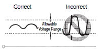
Use a commercial power supply for the power supply voltage input to models with AC inputs.
Inverters with an output frequency of 50/60 Hz are available, but the rise in the internal temperature of the Timer may result in ignition or burning. Do not use an inverter output for the power supply of the Timer.
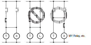
The Timers listed below cannot be directly turned ON and OFF by using an AC 2-wire proximity sensor to turn the Timer's power supply ON and OFF.
Use the following countermeasure when using an AC 2-wire proximity sensor with the Timer. (The power supply circuit in the Timer uses half-wave rectification. Only a half AC wave is supplied to the proximity sensor, which may cause operation to be unstable.)
Applicable Models
H3Y, H3YN, H3RN, H3CA-8, RD2P, and H3CR (-A, -A8, -AP, -F, and -A8E (-A8E: Only for 100 to 240 VAC))
Countermeasure
Wire through a relay and use the relay contacts to turn the power supply ON and OFF.
Confirm the stability of operation after making the connections.
Install protective measures (such as earth leakage breakers, wiring breakers, or fuses) on the power supply side according to any applicable laws or regulations.
Correctly Handling Input Signals
Malfunction due to noise may occur if input wiring is placed in the same duct or conduit as power lines or high-voltage lines. Separate input wiring from power lines and wire them in a separate system.
Also, use shielded cables, use metal conduits, and keep wiring distances as short as possible.
Timers with Relays
Do not connect a load that exceeds contact ratings, such as the switching capacity (contact voltage or contact current). Insulation faults, contact welding, contact faults, and other failures to achieve specified performance may occur and the relay may be damaged or may burn.
Continued use with deteriorated performance may ultimately result in insulation breakdown between circuits or relay burning. The life of the built-in relay is greatly affected by switching conditions.
Before using the Timer, test operation under actual application conditions and confirm that the switching frequency presents no problems in performance.
Electrical life depends on the type of load, switching frequency, and ambient environment. Observe the following precautions when using the Timer. When switching a DC load, contact transfer may cause the contacts to stick or may cause contact failure.
Confirm applicability and consider using a surge absorbing element. When switching at high frequencies, heat generated by arcing may cause contacts to melt or may cause metal corrosion.
Consider connecting an arc absorbing element, reducing the switching frequency, or lowering the humidity.
The surge current depends on the type of load, which also affects contact switching frequency and the number of operations. Check the rated current and the inrush current, and design the circuits with sufficient margin.
| Resistive load | Solenoid load | Motor load | Incandescent lamp load |
| Rated current | 10 to 20 times the rated current | 5 to 10 times the rated current | 10 to 20 times the rated current |
| Sodium light load | Capacitor load | Transformer load | Mercury light load |
| 1 to 3 times the rated load | 20 to 40 times the rated load | 5 to 15 times the rated load | 1 to 3 times the rated load |
Arcing when switching and relay heating may result in ignition or explosion. Do not use the Timer in atmospheres subject to inflammable or explosive gases.
Contact faults may occur. Do not use the Timer in atmospheres subject to sulfidizing gas, chloride gas, or silicon gas.
The switching capacity for DC voltage loads is lower than that for AC voltage loads.
Timers with Non-contact Outputs
Short faults or open faults may occur due to destruction of the output element. Do not use the Timer for a load that exceeds the rated output current.
Short faults or open faults may occur due to destruction of the output element from reverse electromotive force. When using the Timer for a DC inductive load, always connect a diode as a countermeasure against reverse electromotive force.
Other Precautions
Confirm that you have the correct model before using it.
Be sure that all terminals are wired correctly.
Always test the output status with a tester before using a Timer with a built-in keep relay (e.g., the H3CR-H). Shock resulting from dropping the Timer during transport or handling may cause the output contacts to reverse or to be in a neutral status.
The electrolytic capacitor and other internal part may deteriorate quickly if the Timer is left in a timed-out condition (i.e., with the internal relay in an ON state) for a long period of time at high temperatures. Use the Timer in combination with relays and avoid leaving the Timer with the output turned ON for an extended period of time (e.g., for more than a month).
Reference Example (Use the Timer as shown below.)
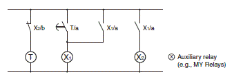
Be sure that only a qualified worker (e.g., an electrical engineer) performs electrical work for the Timer.
Precautions for Correct Use
Operating Time Setting
When setting the operating time, do not turn the setting knob beyond its scale range. For precise time setting, conduct operation tests by adjusting the setting knob.
The accuracy the operating time of the Analog Timer is indicated by the percentage value on the basis of the full-scale time. The absolute fluctuation value will not be improved by changing the time setting. Therefore, when selecting the model, be sure that the application will be able to use a time setting as close as the fullscale time setting of the Timer.
When there are setting changes in the Analog Timers while they are in time-limit operation, the following operation will result.

Control Output
Use a load current for the control output relay contact that is below both the rated current and the load indicated for connection to the load circuit. Otherwise the life of the relay contact will be significantly shortened.
For micro-load switching, check the minimum applicable load that is indicated for each product.
The lifetime for control output relay contacts varies greatly with the switching conditions. Be sure to test the contacts in actual operating conditions prior to using them, then use them within a range of switching cycles that will not cause any problems. If a contact is used after its performance has degraded, it may eventually cause insufficient insulation between circuits or burning damage to the relay itself.
The following are correct and incorrect connection examples. Do not wire the Timer like the incorrect example, otherwise a shortcircuit may occasionally be caused by the Timer's internal contacts that will be different to each other in polarity.
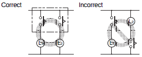
For micro-load switching, check the minimum applicable load that is indicated for each product.
Internal circuit
Impose supply voltage on the Timer through a switch or relay contact at one time. Do not impose supply voltage gradually, otherwise the Timer may go into time-up condition or may not be reset.

Be sure that the capacity of the power supply is large enough, otherwise the Timer may not start due to inrush current that may flow for an instant when the Timer is turned ON. (Refer to Technical Explanation for Timers and Time Switches)
AC power can be applied to the Timer regardless of the polarity of the power supply terminals. When supplying DC power, be careful enough not to make a mistake in polarity.
Faulty operation, abnormal heating, or burning may result from applying a voltage other than the rated voltage, wiring incorrectly, or reversing the polarity when supplying DC power.
Be sure that the ripple rate of DC power supplied to the Timer is within the rated range.
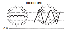
Refer to the following for the ripple rates of typical simple power supplies.
| Rectifying method | Ripple rate |
| Single-phase, full-wave | Approx. 48% |
| Three-phase, full-wave | Approx. 4% |
| Three-phase, half-wave | Approx. 17% |
Note: Refer to the permissible ripple rate of the model to be used.
The Timer can withstand an external impulse voltage with a ±1.2×50-ms standard waveform, imposed between the power supply terminals, which conforms to the Japanese JEC-210 standards. If power surges or noise exists, it may cause damage to internal elements or faulty operation. To prevent this, it is recommended that the waveform be checked, and an appropriate surge absorber be used. The effect of a surge absorber will vary depending on the surge or noise generated, so it must be checked using an actual Timer.
Make sure that no residual voltage or inductive voltage exists when the power is turned OFF.
Setting
When using a key switch for setting, do not use your fingernail or an instrument with a sharp point, otherwise the key may be damaged.
Before changing times or other settings of the Time Swith while power is being supplied, either turn OFF the power on the load side or set the output ON/OFF switch to OFF and confirm the safety of the system.
Others
When conducting a dielectric test, impulse voltage test, or insulation resistance test between electric circuit and non-current-carrying metal parts of the Timer mounted to a control panel, be sure to take the following steps. These steps will prevent the internal circuitry of the Timer from damage that may be caused if a machine on the control panel has an improper dielectric strength or insulation resistance.
1. Separate the Timer from the circuits of the control panel.
(Either remove the Counter from the Socket or disconnect the wires.)
2. Short-circuit all terminals of the Timer.
If any device with no-contact output, such as a proximity sensor, photoelectric sensor, or SSR, is directly connected to the Timer, current leakage from the device may cause Timer malfunction. Be sure to test the device with the Timer before using the device for actual applications.
Disconnect the wiring before replacing the battery. Touching parts to which a high voltage is applied may result in electric shock.
Before using the Timer to switch inductive loads, be sure to connect a surge absorbing element to the Timer in order to prevent the Timer from malfunction and damage. A diode is an example of a surge absorbing element for DC circuits and a surge absorber is an example of a surge absorbing element for AC circuits.
Examples of Surge Suppressor
| Circuit example | Applicability | Features and remarks | Element selection | ||
| AC | DC | ||||
| CR |  | * (OK) | OK | Load impedance must be much smaller than the CR impedance when the Relay operates on an AC voltage. When the contact is open, the current flows through C and R to the inductive load. | Use the following as guides for C and R values: C: 0.5 to 1 μF for a 1-A contact current R: 0.5 to 1 Ω for 1-V contact voltage However, these values may depend on numerous factors, including the type of load and variations in characteristics. Confirm optimum values experimentally. Remember that capacitor C suppresses the discharge when the contacts are opened, while the resistor R limits the current applied when the contacts are closed the next time. Generally, use a capacitor with a dielectric strength of 200 to 300 V. When it is to be used in an AC circuit, use an AC capacitor (with no polarity). However, if there is any question about the ability to extinguish the arcing of the contacts when it is to be used in a high DC voltage, it may be more effective to connect the capacitor and resistor across the contacts, rather than across the load. Perform testing with the actual equipment to determine this. |
 | OK | OK | The release time of the contacts will be longer when a relay or solenoid is used as the load. | ||
| Diode |  | NG | OK | The energy stored in a coil (inductive load) reaches the coil as current via the diode connected in parallel with the coil, and it is consumed as joule heat by the resistance of the inductive load. This type of circuit lengthens the release time more than the CR type. | Use a diode having a reverse breakdown voltage of more than 10 times the circuit voltage, and a forward current rating greater than the load current. A diode having a reverse breakdown voltage two or three times that of the supply voltage can be used in an electronic circuit where the circuit voltage is not particularly high. |
| Diode + Zener diode |  | NG | OK | This circuit effectively shortens release time in applications where the release time of a diode protection circuit is too slow. | The breakdown voltage to the Zener diode should be about the same as the supply voltage. |
| Varistor |  | OK | OK | This circuit prevents a high voltage from being applied across the contacts by using the constant-voltage characteristic of a varistor. This circuit also somewhat lengthens the release time. This circuit is effective if connected across the load when the supply voltage is 24 to 48 V. If the supply voltage is 100 to 240 V, connect the circuit across the contacts. | The cutoff voltage Vc must satisfy the following conditions. For AC, it must be multiplied by √2. Vc > (Supply voltage × 1.5) However, if Vc is set too high, its effectiveness will be reduced because it will fail to cut off high voltages. |
Do not use the following types of surge suppressors.
 | This circuit arrangement is very effective for diminishing arcing at the contacts when breaking the circuit. However, electrical energy is stored in C (capacitor) when the contacts are open, so the current from C flows into the contacts when they close. This may lead to contact welding. |  | This circuit arrangement is very useful for diminishing arcing at the contacts when breaking the circuit. However, the charging current to C flows into the contacts when they are closed, so contact welding may occur. |
Note: Although it is considered that switching a DC inductive load is more difficult than a resistive load, an appropriate surge suppressor can achieve almost the same characteristics.
When the Timer is reset right after the Timer goes into time-up condition, be sure to provide the Timer with an appropriate circuit configuration considering the resetting time of the Timer so that a sequential error will not result.
Example: ON-delay operation
The Digital Timer uses the constant value read method. Be careful when changing the set value because the output of the Digital Timer will be ON when the set value coincides with the count value.
Mounting
Surface Mounting
There is no particular restriction on surface mounting directions, but be sure that the Timer is securely mounted horizontally.
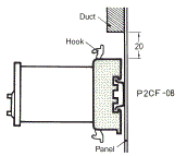
P2CF Socket
When mounting the Timer vertically with the P2CF Socket, consider the movable hooks and be sure that there is a 20-mm space on each of the upper and lower parts of the Socket.
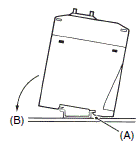
Track Mounting (H3CA-FA)
1. Hook portion (A) onto one rail and press the Timer in the (B) direction.
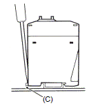
2. When dismounting the Timer, insert a flat-blade screwdriver into portion (C) and remove the Timer.
PL Socket
1. Insert the PL Socket from the panel surface and secure the L-shaped hooks of the Socket with screws.
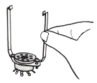
2. Connect the Timer to the Socket and press the tip of each hook by hand.
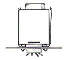
Using a Mounting Bracket (H5L)
1. Attach the Mounting Bracket to the Time Switch.
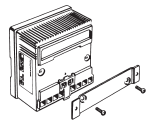
2. Secure the Mounting Bracket to the mounting surface with the holes provided at both ends of the Mounting Bracket.
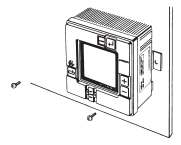
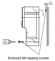
Using Screws (H5F-FA/FB)
1. Use the enclosed, M4 tapping screws to mount the Time Switch.
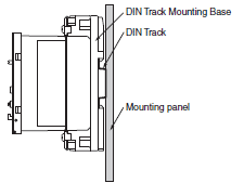
DIN Track Mounting with DIN Track Mounting Base (H5S-FA/FB)
1. Attach the enclosed DIN Track Mounting Base to the Time Switch.
2. Attach the mounting section on the enclosed DIN Track Mounting Base to the DIN Track.
PF085A or P2B Socket (1)
1. Mount the Socket to the panel surface and insert the F-shaped hook into the sockets.
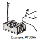
2. Connect the Timer to the Socket and press the tip of each hook by hand.
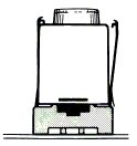
PF85A Socket (2)
1. Secure the Socket to the panel surface with screws and insert the F-shaped hook into the sockets.
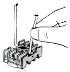
2. Connect the Timer to the Socket and press the tip of each hook by hand.
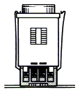
8PFA Socket
Mount a Y92F-42 Base Adapter to the 8PFA Socket.

Fit a socket-type 48-mm x 48-mm Timer from above. The Adapter uses hooks to secure the Timer. It does not serve to convert the wiring.
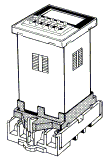
Flush Mounting
The mounting panel must be 1.0 to 3.2 mm in thickness, and varies with the model. Refer to the precautions for each model for details.
When the Y92F-30 Flush Mounting Adapter is used, insert the Timer into the square hole from the front side of the panel and attach the Flush Mounting Adapter from the rear side of the Timer. Press on the Flush Mounting Adapter so that the space between the Flush Mounting Adapter and the panel is reduced as much as possible, and secure the Flush Mounting Adapter with screws.
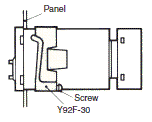
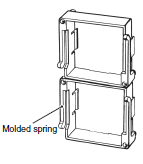
When multiple Timers are closely mounted vertically, be sure that the molded springs of each Y92F-30 Flush Mounting Adapter are locatedon the left and right sides.
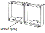
When multiple Timers are closely mounted horizontally, be sure that the molded springs of each Y92F-30 Flush Mounting Adapter are located on the top and bottom sides.
When using the US08, be sure to use 10.5-mm-dia. max. multiconductor cable or 3-mm-dia. max. insulated stranded wire for wiring.
When the Y92F-40, Y92F-70, Y92F-71, Y92F-73, or Y92F-74 Flush Mounting Adapter is used, just insert the Timer into the square panel hole. If the panel coating is too thick and the hooks do not click, spread open the hooks appropriately to the left and right after inserting the Timer to the hole.
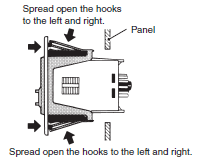
The illustration is an example with the Y92F-70.
Dismounting
Surface Mounting with P2CF
Use your thumb to release the hook.
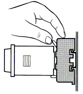
Surface Mounting with PF085A
Use your thumb to release the hook while pressing on the hook with your index finger.
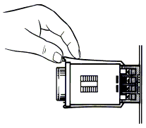
Panel Mounting
Loosen the screws of the Flush Mounting Adapter, spread open the hooks, and remove the Mounting Adapter.
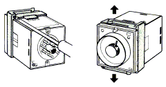
When the Y92F-40, Y92F-70, Y92F-71, Y92F-73, or Y92F-74 Mounting Adapter is used, press the hook inwards with the thumb and index finger of both hands, and press the Timer towards the front side.
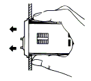
Check Items for Timer Model Selection
1. Power supply voltage
2. Power consumption
3. Operating and resetting methods
4. Contact configuration and capacity
5. Operating time range
6. Resetting time
7. Mechanical and electrical life
8. Operating environment, such as temperature, humidity, dust, vibration, and shock
9. Peripheral power supply environment, such as peripheral devices and permissible voltage fluctuation range
10.Operating frequency
11.Setting frequency and type (time or timing setting)
12.Accuracy of operating time
13.Mounting method and direction
14.Size restriction