 Cautions
-
 Sensors
-
 Fiber Sensors
-
 Photoelectric Sensors
- Displacement Sensors / Measurement Sensors
-
 Proximity Sensors
-
 Photomicro Sensors
-
 Rotary Encoders
-
 Pressure Sensors / Flow Sensors
-
 Ultrasonic Sensors
-
Displacement Sensors / Measurement Sensors
|
|
|
|
| Safety Precautions |
Safety Precautions for All Displacement Sensors
For precautions on individual products, refer to Safety Precautions in individual product information.
This page explains the precautions applied to optical displacement sensors only.
Regarding the precautions applied to sensors with other methods and operating principles, refer to Safety Precautions in individual product information.

These products cannot be used in safety devices for presses or other safety devices used to protect human life. These products are designed for use in applications for sensing workpieces and workers that do not affect safety.


Mounting
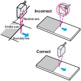
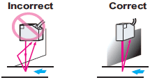
Displacement measurement of objects with differing materials and color.
If the material or color of objects is noticeably different, measurement error can be reduced by mounting the sensor so that the line joining the emitter axis and the receiver axis is parallel to the boundary line of the objects, as shown in the diagram below.
Measuring displacement in narrow grooves and depressions
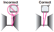
If the object to be measured is in a depression or groove with wall-like sides, mount the sensor as shown in the diagram below so that the emitter axis and the receiver axis are not obstructed by the wall-like sides.
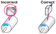
Displacement measurement of rotating objects
To measure rotating objects, the effects of vertical variations and positional variations can be minimized by mounting the sensor so that the line joining the emitter axis and the receiver axis is parallel to the axis of rotation.
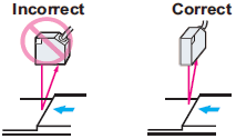
Displacement measurement of objects with a step-like level difference.
If the object to be measured has a step-like level difference, the effects of the step edge can be minimized by mounting the sensor so that the line joining the emitter axis and the receiver axis is parallel to the step edge.
Sensor head and peripheral walls
Light reflected from a wall will cause error. If the sensor must be mounted near a wall, mount the sensor so that the line joining the emitter axis and the receiver axis is parallel to the wall, as shown in the diagram below. Painting the wall a dull black will also help reduce reflection.
Wiring
About wiring
Do not use a current in excess of the rated current. This will damage the product.
Do not reverse the power supply connection or connect to an AC current.
Do not short-circuit the load of an open collector output.
Wire this product separately from high-voltage wires and power lines. If wired together or in the same conduit, induction may cause incorrect operation and damage.
If a commercial switching regulator is used, ground the FG (frame ground) terminal.
Work Required for Unconnected Leads
Unused leads should be cut and wrapped with insulating tape to prevent contact with other terminals.
Cable
The insulated part of the cable terminal is used for our internal characteristic inspections. This section is not covered by our warranty. Please cut and process the insulated part of the cable terminal (brown, blue, black, etc.) before use.
Operating Environment
Ambient Conditions
At low temperatures (0°C or less), the vinyl cable will harden and the wires may break if the cable is bent. Do not bend a Standard or Robot Cable at low temperature.
Refer to the Displacement sensor datasheets and manuals for details.
Safety Precautions for All Measurement Sensors
For precautions on individual products, refer to Safety Precautions in individual product information.

These products cannot be used in safety devices for presses or other safety devices used to protect human life.
These products are designed for use in applications for sensing workpieces and workers that do not affect safety.


Designing
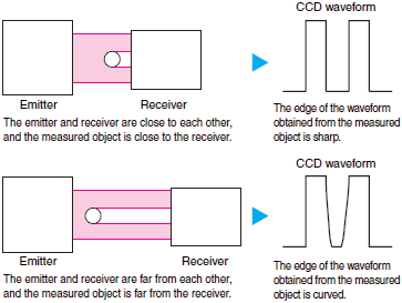
Measured Distance and Accuracy (CCD Method)
The accuracy of a sensor that employs a CCD image sensor as the light receiving element, such as the ZX-GT, varies inversely with the distance between the emitter and receiver, and with the distance between the measured object and receiver. If the distance is too great, the edge of the shadow cast by the measured object becomes blurred due to light diffraction, and the sensor measures it as error. If the installation conditions allow, use the sensor so that the emitter and receiver, and the measured object and receiver, are close to each other.
Wiring
About wiring
Do not use a current in excess of the rated current. This will damage the product.
Do not reverse the power supply connection or connect to an AC current.
Do not short-circuit the load of an open collector output.
Wire this product separately from high-voltage wires and power lines. If wired together or in the same conduit, induction may cause incorrect operation and damage.
If a commercial switching regulator is used, ground the FG (frame ground) terminal.
Work Required for Unconnected Leads
Unused leads should be cut and wrapped with insulating tape to prevent contact with other terminals.
Cable
The insulated part of the cable terminal is used for our internal characteristic inspections. This section is not covered by our warranty. Please cut and process the insulated part of the cable terminal (brown, blue, black, etc.) before use.
Operating Environment
Ambient Conditions
At low temperatures (0°C or less), the vinyl cable will harden and the wires may break if the cable is bent. Do not bend a Standard or Robot Cable at low temperature.
Refer to the Measurement sensor datasheets and manuals for details.