The specifications shown in the following table apply to all the CS-series Process Analog I/O Units.
CS1W-PDC / PTW / PTR
SYSMAC CS-series Process Analog I/O Units
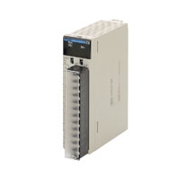
Provides the functionality of isolators, power supplies, signal converters, and other devices.
Related Contents
- Programmable Controllers
- Features
- Lineup
- Specifications
- Dimensions
- Catalog
last update: September 24, 2012
General Specifications
| Item | Specification |
|---|---|
| Applicable PLC | CS-series PLCs |
| Unit type | CS-series Special I/O Unit |
| Structure | Backplane-mounted, single slot size |
| Dimensions | 35 × 130 × 126 mm (W × H × D) |
| Weight | 450 g max. |
| External connection terminals | CS1W-PDC55 24-point removable terminal block (with lever) (M3 screws, Tightening torque: 0.5 Nm) Other Units 21-point removable terminal block (M3 screws, Tightening torque: 0.5 Nm) |
| Unit number switch setting | 00 to 95 |
| Self-diagnosis function | Results of self-diagnosis shown on indicators. |
| Mountable Racks | CPU Rack or CS-series Expansion Rack |
| Maximum number of Units | 80 Units (10 Units × 8 Racks) Confirm that the total current consumption of all the Units (including the CPU Unit) mounted to a single CPU Rack or Expansion Rack does not exceed the maximum power supply capacity of the Power Supply Unit. |
| Ambient operating temperature | 0 to 55 ° C |
| Ambient operating humidity | 10% to 90% (with no condensation) |
Current consumption
| Name | Model | Current consumption (power) | |
|---|---|---|---|
| 5 V | 26 V | ||
| Isolated-type 2-Wire Transmitter Input Unit | CS1W-PTW01 | 0.15 A (0.75 W) | 0.16 A (4.2 W) |
| Isolated-type Direct Current Input Unit | CS1W-PDC01 | 0.15 A (0.75 W) | 0.16 A (4.2 W) |
| CS1W-PDC11 | 0.12 A (0.60 W) | 0.12 A (3.12 W) | |
| CS1W-PDC55 | 0.18 A (0.90 W) | 0.06 A (1.56 W) | |
| Power Transducer Input Unit | CS1W-PTR01 | 0.15 A (0.75 W) | 0.08 A (2.1 W) |
| Analog Input Unit (100 mV) | CS1W-PTR02 | 0.15 A (0.75 W) | 0.08 A (2.1 W) |
(Reference) Maximum current and total power supplied
| Power Supply Unit | Maximum current supplied (power) | Maximum total power | ||
|---|---|---|---|---|
| 5 V | 26 V | 24 V | ||
| C200HW-PA204 | 4.6 A (23 W) | 0.6 A (15.6 W) | None | 30 W |
| C200HW-PA204C | 4.6 A (23 W) | 0.6 A (15.6 W) | None | 30 W |
| C200HW-PA204S | 4.6 A (23 W) | 0.6 A (15.6 W) | 0.8 A (19.2 W) | 30 W |
| C200HW-PA204R | 4.6 A (23 W) | 0.6 A (15.6 W) | None | 30 W |
| C200HW-PD024 | 4.6 A (23 W) | 0.6 A (15.6 W) | None | 30 W |
| C200HW-PA209R | 9 A (45 W) | 1.3 A (33.8 W) | None | 45 W |
| C200HW-PD025 | 5.3 A | 1.3 A | None | 40 W |
| CS1D-PA207R | 7 A (35 W) | 1.3 A (33.8 W) | None | 35 W |
| CS1D-PD024 | 4.3 A (21.5 W) | 0.56 A (14.6 W) | None | 28 W |
| CS1D-PD025 | 5.3 A | 1.3 A | None | 40 W |
CS1W-PDC01 Isolated-type Direct Current Input Unit
| Item | Specifications | ||
|---|---|---|---|
| Model | CS1W-PDC01 | ||
| Applicable PLC | CS-series | ||
| Unit type | CS-series Special I/O Unit | ||
| Mounting position | CS-series CPU Rack or CS-series Expansion Rack (Cannot be mounted to C200H Expansion I/O Rack or
SYSMAC BUS Remote I/O Slave Rack.) |
||
| Maximum number of
Units |
80 (within the allowable current consumption and power consumption range) | ||
| Unit numbers | 00 to 95 (Cannot duplicate Special I/O Unit numbers.) | ||
| Areas for
data exchange with CPU Unit |
Special I/O
Unit Area |
10 words/Unit
Isolated-type Direct Current Input Unit to CPU Unit: All process values, process value alarms (LL, L, H, HH), rate-of-change values, rate-of-change alarms (L, H), input errors |
|
| DM Area
words allocated to Special I/O Units |
100 words/Unit
CPU Unit to Isolated-type Direct Current Input Unit: Input signal type, scaling of process values in industrial units, square root function enable, rate-of-change value range, rate-of-change scaling, number of items for moving average, process value alarm setting (LL, L, H, HH), rate-of-change alarm setting (L, H), zero/span adjustment value, etc. |
||
| Number of inputs | 4 | ||
| Input signal type | 4 to 20 mA, 0 to 20 mA, - 10 to 10 V, 0 to 10 V,
- 5 to 5 V, 1 to 5 V, 0 to 5 V, or ± 10-V user-set range. The ± 10-V user-set range can be specified within - 10.000 to 10.000 V. |
Input signal type and scaling to industrial units are
separate for each of the 4 inputs. Note: Input signal type and scaling to industrial units are set in the DM Area. Example: Input signal type: 4 to 20 mA; industrial unit scaling: 0 to 500 m 3 /h (after square root extraction). DM Area settings are as follows: Input signal type: 5 (0005 hex) Industrial unit maximum value stored: 500 (01F4 hex) Industrial unit minimum value stored: 0 (0000 hex) |
|
| User-defined scaling in
industrial units |
Scaling required for the above input signals, such as
4 to 20 mA or 1 to 5 V. (Any minimum and maximum values can be set.) (4 inputs set separately.) |
||
| Data storage in the
CIO Area |
The value derived from carrying out the following
processing in order of the process value data is stored in four digits hexadecimal (binary values) in the allocated words in the CIO Area. 1) Mean value processing → 2) Scaling → 3) Zero/ span adjustment → 4) Square root extraction → 5) Output limits |
||
| Accuracy (25 ° C) | ± 0.1% of full scale
For the ± 10-V user-set range, however, as shown in the following equation, the accuracy depends on the ratio of the selected internal range (0 to 4) span to the user-set range span.  |
||
| Temperature
coefficient |
± 0.015% / ° C with respect to full scale.
For the ± 10-V user-set range, however: ± 0.015% / ° C with respect to the internal range. |
||
| Resolution | 1/4,096 of full scale
For the ± 10-V user-set range, however, as shown in the following equation, the resolution depends on the ratio of the selected internal range (0 to 4) span to the user-set range span.  |
||
| Input signal range | For inputs of 4 to 20 mA, 0 to 20 mA, 0 to 10 V, 1 to 5 V, 0 to 5 V: - 15 to 115%
For inputs of - 10 to 10 V or - 5 to 5 V: - 7.5 to 107.5% For ± 10-V user-set range: - 7.5 to 107.5% of internal range |
||
| Input impedance | For current input: 250 Ω
For voltage input: 1 MΩ min. |
||
| Warmup time | 10 min | ||
| Response time | 0.5 s (travel time from input 0% to 90%, for step input) | ||
| Conversion period | 100 ms/4 inputs | ||
| Maximum time to store
data in CPU Unit |
Conversion period + one CPU Unit cycle | ||
| Input error detection | Checks are conducted for only 4 to 20 mA and 1 to 5 V.
Error detected when under - 17.2% (1.25 mA, 0.3125 V) or over 112.5% (22 mA, 5.5 V). |
||
| Operation at input
disconnection |
4 to 20 mA, 1 to 5 V: Process value of - 15% stored.
0 to 20 mA, 0 to 5 V, 0 to 10 V, - 10 to 10 V: The same value is stored as when 0 V or 0 mA is input. |
||
| Input disconnection
overrange time |
Approx. 1 s | ||
| Function | Mean value
processing (input filter) |
Calculates the moving average for the specified number of past process values (1 to 16), and stores that
value in the CIO Area as the process value. |
|
| Process
value alarm |
Process value 4-point alarm (HH, H, L, LL), hysteresis, and ON-delay timer (0 to 60 s) are available. | ||
| Rate-of-
change calculation |
Calculates the amount of change per comparison time interval (1 to 16 s). | ||
| Rate-of-
change alarm |
Rate-of-change 2-point alarm (H, L), alarm hysteresis (shared with process value alarm), and ON-delay
timer (0 to 60 s, shared with process value alarm) are available. |
||
| Square
root |
When the process value scaling maximum value is A and the minimum value is B:

Dropout: Output approx. 7% maximum linear (output = input) characteristics Note: The square root function is only enabled when the maximum scaling value is greater than the minimum value. Note: When square root processing is being performed, set the maximum and minimum scaling values to the values required after square root processing of the current or other input values. |
||
| Isolation | Between analog inputs and between input terminals and PLC signals: Isolation by transformer | ||
| Insulation resistance | 20 MΩ (at 500 V DC) between inputs | ||
| Dielectric strength | Between inputs: 1,000 V AC, at 50/60 Hz, for 1 min, leakage current 10 mA max. | ||
| External connections | Terminal block (detachable) | ||
| Unit number settings | Set by rotary switches on front panel, from 0 to 95. | ||
| Indicators | Three LED indicators on front panel (for normal operation, errors detected at the Direct Current Input Unit,
and errors related to the CPU Unit). |
||
| Front panel connector | Sensor input connector terminal block (detachable) | ||
| Effect on CPU Unit cycle
time |
0.3 ms | ||
| Current consumption | 5 V DC at 150 mA max., 26 V DC at 160 mA max. | ||
| Dimensions | 35 × 130 × 126 mm (W × H × D)
Note: The height including the Backplane is 145 mm. |
||
| Weight | 450 g max. | ||
| Standard accessories | None | ||
CS1W-PDC11 Isolated-type Direct Current Input Unit
| Item | Specifications | |
|---|---|---|
| Model | CS1W-PDC11 | |
| Applicable PLC | CS Series | |
| Unit type | CS-series Special I/O Unit | |
| Mounting position | CS-series CPU Rack or CS-series Expansion Rack (Cannot be mounted to C200H Expansion I/O Rack or
SYSMAC BUS Remote I/O Slave Rack.) |
|
| Maximum number of
Units |
80 (within the allowable current consumption and power consumption range) | |
| Unit numbers | 00 to 95 (Cannot duplicate Special I/O Unit numbers.) | |
| Areas for
data exchange with CPU Unit |
Special I/O
Unit Area |
10 words/Unit
Isolated-type Direct Current Input Unit to CPU Unit: All process values, process value alarms (LL, L, H, HH), rate-of-change values, rate-of-change alarms (L, H), disconnection alarms, cold junction sensor errors, adjustment period end/notice |
| DM Area
words allocated to Special I/O Units |
100 words/Unit
CPU Unit to Isolated-type Direct Current Input Unit: Input signal type, scaling of process value in industrial units, process value alarm setting (L, H), inrush input upper limit, inrush input upper limit time, zero/span adjustment value, Square root function. Temperature input signal type, input range (user set), scaling of process value data to be stored in allocated words in CIO area, rate-of-change input range, scaling of rate-of-change data, number of items for moving average, process value alarm setting (LL, L, H, HH), rate-of-change alarm setting (L, H), zero/span adjustment value |
|
| Expansion
Control/ Monitor Area |
35 words/Unit
CPU Unit to Isolated-type Direct Current Input Unit: Bits for beginning or resetting the hold function selection, adjustment period control, control bits Isolated-type Direct Current Input Unit to CPU Unit: Adjustment period notices, peak and bottom values, top and valley values, integral values |
|
| Expansion
Setting Area |
46 words/Unit
CPU Unit to Isolated-type Direct Current Input Unit: Expansion Setting Area settings, adjustment period control, peak and bottom detection, top and valley detection, integral value calculation |
|
| Number of inputs | 4 | |
| Input signal type | 4 to 20 mA, 0 to 20 mA, 0 to 10 V, - 10 to 10 V, 0 to 5 V, - 5 to 5 V, 1 to 5 V, 0 to 1.25 V, - 1.25 to
1.25 V (separate for each input), and ± 10-V user-set range (specified range within - 10.000 V to 10.000 V) |
|
| Scaling | Data to be stored in the allocated words in the CIO area must be scaled (Any minimum and maximum values
can be set.) (4 inputs set separately.) Data can be converted at 0% to 100%. |
|
| Data storage in the
CIO Area |
The value derived from carrying out the following processing in order of the actual process data in the input
range is stored in four digits hexadecimal (binary values) in the allocated words in the CIO Area. 1) Mean value processing → 2) Scaling → 3) Zero/span adjustment → 4) Square root calculation → 5) Output limits |
|
| Accuracy (25 ° C) | ± 0.05% | |
| Temperature
coefficient |
± 0.008%/ ° C | |
| Resolution | 1/64,000 | |
| Input signal range | For 4 to 20 mA, 0 to 20 mA, 0 to 10 V, 0 to 5 V, 1 to 5 V, 0 to 1.25 V inputs: - 15 to 115%
For - 10 to 10 V, - 5 to 5 V, - 1.25 to 1.25 V inputs: - 7.5 to 107.5% |
|
| Input impedance | For current inputs: 250 Ω (typical)
For voltage inputs: 1 MΩ min. |
|
| Warmup time | 10 min | |
| Response time | 100 ms (travel time from input 0% to 90%, for ± 10 V step input and with moving average for 4 samples) | |
| Conversion period | 20 ms/4 inputs, 10 ms/2 inputs, selectable in words allocated to the Unit as a Special I/O Unit. | |
| Maximum time to store
data in CPU Unit |
Conversion period + one CPU Unit cycle | |
| Input error detection | Check only for 4 to 20 mA and 1 to 5 V.
Error detected for - 17.2% (1.25 mA, 0.3125 V) or less and 112.5% (22 mA, 5.5 V) or more. |
|
| Operation at input
disconnection |
For 4 to 20 mA and 1 to 5 V: Stores - 15% process value.
For all other ranges: Stores same process value as 0-V or 0-mA inputs. |
|
| Input disconnection
overrange time |
Approx. 1 s. | |
| Function | Mean value
processing (input filter) |
Calculates the moving average for the past specified number of process values (1 to 128 can be specified),
and stores that value in the CIO Area as the process value. |
| Process
value alarm |
Process value 4-point alarm (LL, L H, HH), hysteresis, and ON-delay timer (0 to 60 s) are available. | |
| Rate-of-
change calculation |
Calculates the amount of change per comparison time interval (1 to 16 s). | |
| Rate-of-
change alarm |
Rate-of-change 2-point alarm (H, L), alarm hysteresis, and ON-delay timer (0 to 60 s are available, shared
with process value alarm). |
|
| Square
root calculation |
When the maximum value for process value scaling is A and the minimum value is B,

Drop-out: Output approx. 7% max. linear (output = input) characteristic Note 1. The square root function can only be used when the maximum scaling value is greater than the minimum scaling value. The square root will not be found if the maximum is smaller than the minimum. Note 2. When the square root function is used, set the scaling values after square root calculation (e.g., for flow rates or other values) for the process value scaling A and B settings. |
|
| Adjustment
period control |
When zero/span adjustment is executed, the date is internally recorded at the Unit. When the preset
zero/span adjustment period and the notice of days remaining set in the Expansion Setting Area have elapsed, this function turns ON a warning flag to give notice that it is time for readjustment. |
|
| Peak and
bottom detection |
Detects the maximum (peak) and minimum (bottom) analog input values, from when the Hold Start Bit
(output) allocated to the Expansion Control/Monitor Area turns ON until it turns OFF. These values are stored as the peak and bottom values in the Expansion Control/Monitor Area. |
|
| Top and
valley detection |
This function detects the top and valley values for analog inputs, from when the Hold Start Bit (output)
allocated to the Expansion Control/Monitor Area turns ON until it turns OFF. These values are stored as the top and valley values in the Expansion Control/Monitor Area. |
|
| Integral
value calculation |
This function calculates the analog input value's time integral. The integral value is calculated and output
to the Expansion Control/Monitor Area when the Integral Value Calculation Start Bit in the Expansion Control/Monitor Area is turned ON. |
|
| Isolation | Between inputs and between inputs and PLC signals: Isolation by transformer and photocoupler. | |
| Insulation resistance | 20 MΩ (at 500 V DC) between all inputs | |
| Dielectric strength | Between inputs: 1,000 V AC, at 50/60 Hz, for 1 min, leakage current 10 mA max. | |
| External connections | Terminal block (detachable) | |
| Unit number settings | Set by rotary switches on front panel, from 0 to 95. | |
| Indicators | Three LED indicators on front panel (for normal operation, errors detected at the Direct Current Input Unit,
and errors detected at the CPU Unit). |
|
| Front panel connector | Sensor input connector terminal block (detachable) | |
| Effect on CPU Unit cycle
time |
0.3 ms | |
| Current consumption | 5 V DC at 120 mA max., 26 V DC at 120 mA max. | |
| Dimensions | 35 × 130 × 126 mm (W × H × D)
Note: The height including the Backplane is 145 mm. |
|
| Weight | 450 g max. | |
| Standard accessories | Short bars (for current input) | |
CS1W-PDC55 Isolated-type Direct Current Input Unit
| Item | Specifications | ||
|---|---|---|---|
| Model | CS1W-PDC55 | ||
| Applicable PLC | CS Series | ||
| Unit type | CS-series Special I/O Unit | ||
| Mounting position | CS-series CPU Rack or CS-series Expansion Rack (Cannot be mounted to C200H Expansion I/O Rack or
SYSMAC BUS Remote I/O Slave Rack.) |
||
| Maximum number of
Units |
80 (within the allowable current consumption and power consumption range) | ||
| Unit numbers | 00 to 95 (Cannot duplicate Special I/O Unit numbers.) | ||
| Areas for
data exchange with CPU Unit |
Special I/O
Unit Area |
10 words/Unit
Isolated-type Direct Current Input Unit to CPU Unit: All process values, process value alarms (L, H), conversion data enabled flags, input errors |
|
| DM Area
words allocated to Special I/O Units |
100 words/Unit
CPU Unit to Isolated-type Direct Current Input Unit: Input signal type (separate for each input), process value alarm setting (L, H), zero/span adjustment value, Square root function. |
||
| Expansion
Control/ Monitor Area |
1 word/Unit
CPU Unit to Isolated-type Direct Current Input Unit: Process value alarms |
||
| Number of inputs | 8 | ||
| Input signal type | 0 to 10 V, 0 to 5 V, 1 to 5 V, 4 to 20 mA (separate
for each input). ("Not used" can be selected). |
Input signal type and scaling to industrial units are
separate for each of the 8 inputs. Note: Input signal type and scaling to industrial units are set in the DM Area. Example: Input signal type: 4 to 20 mA; industrial unit scaling: 0 to 500 m 3 /h (after square root extraction). DM Area settings are as follows: Input signal type: 3 (0003 hex) Industrial unit maximum value stored: 500 (01F4 hex) Industrial unit minimum value stored: 0 (0000 hex) |
|
| Scaling | Data to be stored in the allocated words in the CIO
area must be scaled (Any minimum and maximum values can be set.) (8 inputs set separately.) Data can be converted at 0% to 100%. |
||
| Data storage in the
CIO Area |
The value derived from carrying out the following
processing in order of the actual process data in the input range is stored in four digits hexadecimal (binary values) in the allocated words in the CIO Area. 1) Scaling → 2) Zero/span adjustment → 3) Square root calculation → 4) Output limits |
||
| Accuracy (25 ° C) | ± 0.3% of full scale | ||
| Temperature
coefficient |
For voltage inputs: 100 ppm/ ° C of full scale.
For current inputs: 120 ppm/ ° C of full scale. |
||
| Resolution | 1/16,000 of full scale | ||
| Input signal range | For all inputs: - 5 to +105% | ||
| Input impedance | For current inputs: 250 Ω (typical)
For voltage inputs: 1 MΩ min. |
||
| Warmup time | 10 min | ||
| Conversion period | 250 ms/8 inputs | ||
| Maximum time to store
data in CPU Unit |
Conversion period + one CPU Unit cycle | ||
| Input error detection | Detects sensor error at each input and turns ON the Sensor error Flag.
The process value overrange direction for when a sensor error occurs can be specified. (High: 105% of input range; low: - 5% of input range) |
||
| Function | Process
value alarm |
Process value 8-point alarm (L H), hysteresis, and ON-delay timer (0 to 60 s) are available.
Two alarms per input (L, H) can be output to addresses in the CIO Area specified in the Expansion Setting Area. |
|
| Square root
calculation (Supported only when input is 1 to 5 V or 4 to 20 mA.) |
When the maximum value for process value scaling is A and the minimum value is B,

Drop-out: Output approx. 7% max. linear (output = input) characteristic Note 1. The square root function can only be used when the maximum scaling value is greater than the minimum scaling value. The square root will not be found if the maximum is smaller than the minimum. Note 2. When the square root function is used, set the scaling values after square root calculation (e.g., for flow rates or other values) for the process value scaling A and B settings. |
||
| Isolation | Between inputs and between inputs and PLC signals: Isolation by transformer and photocoupler. | ||
| Insulation resistance | 20 MΩ max. (at 500 V DC).
Between all input terminals and external AC terminals (Power Supply Unit) Between all input terminals and FG plate |
||
| Dielectric strength | Between all input terminals and external AC terminals (Power Supply Unit)
Between all input terminals and FG plate 1,000 VAC, 50/60 Hz 1 min., detection current: 1 mA Between all channels 500 VAC, 50/60 Hz 1 min., detection current: 1 mA |
||
| External connections | Terminal block (detachable) | ||
| Unit number settings | Set by rotary switches on front panel, from 0 to 95. | ||
| Indicators | Three LED indicators on front panel (for normal operation, errors detected at the Direct Current Input Unit,
and errors detected at the CPU Unit). |
||
| Front panel connector | Sensor input connector terminal block (detachable) | ||
| Effect on CPU Unit cycle
time |
0.4 ms | ||
| Current consumption | 5 V DC at 180 mA max., 26 V DC at 60 mA max. | ||
| Dimensions | 35 × 130 × 126 mm (W × H × D)
Note: The height including the Backplane is 145 mm. |
||
| Weight | 450 g max. | ||
CS1W-PTW01 2-Wire Transmitter Input Unit
| Item | Specifications | ||
|---|---|---|---|
| Model | CS1W-PTW01 | ||
| Applicable PLC | CS Series | ||
| Unit type | CS-series Special I/O Unit | ||
| Mounting position | CS-series CPU Rack or CS-series Expansion Rack (Cannot be mounted to C200H Expansion I/O Rack or
SYSMAC BUS Remote I/O Slave Rack.) |
||
| Maximum number of
Units |
80 (within the allowable current consumption and power consumption range) | ||
| Unit numbers | 00 to 95 (Cannot duplicate Special I/O Unit numbers.) | ||
| Areas for
data exchange with CPU Unit |
Special I/O
Unit Area |
10 words/Unit
2-Wire Transmitter Input Unit to CPU Unit: All process values, process value alarms (LL, L, H, HH), rate-of-change values, rate-of-change alarms (L, H), input errors |
|
| DM Area
words allocated to Special I/O Units |
100 words/Unit
CPU Unit to 2-Wire Transmitter Input Unit: Sensor type, scaling of process value data to be stored in allocated words in CIO area, square root function enable, rate-of-change value range, rate-of-change scaling, number of items for moving average, process value alarm setting (LL, L, H, HH), rate-of-change alarm setting (L, H), zero/span adjustment value, etc. |
||
| Number of inputs | 4 | ||
| Sensor type | Unified signal from transmitter (4 to 20 mA), 4 to
20 mA, 1 to 5 V |
Sensor type and scaling to industrial units are
separate for each of the 4 inputs. Note: Sensor type and scaling to industrial units are set in the DM Area. Example: Input signal type: 4 to 20 mA from 2-wire transmitter; industrial unit scaling: 0 to 500 m 3 /h (after square root extraction). DM Area settings are as follows: Input signal type: 0 (0000 hex) Industrial unit maximum value stored: 500 (01F4 hex) Industrial unit minimum value stored: 0 (0000 hex) |
|
| User-defined scaling in
industrial units |
Scaling required for 4 to 20 mA or 1 to 5 V. (Any
minimum and maximum values can be set.) (4 inputs set separately.) |
||
| Data storage in the
CIO Area |
The value derived from carrying out the following
processing in order of the process value data is stored in four digits hexadecimal (binary values) in the allocated words in the CIO Area. 1) Mean value processing → 2) Scaling → 3) Zero/ span adjustment → 4) Square root extraction → 5) Output limits |
||
| Accuracy (25 ° C) | ± 0.2% of full scale | ||
| Temperature
coefficient |
± 0.015%/ ° C of full scale | ||
| Resolution | 1/4,096 of full scale | ||
| Input signal range | - 15 to 115% | ||
| Power supply for 2-wire
transmitter |
Output voltage: 24 V DC ± 15% for each input (without load)
Current capacity: 22 mA max. for each input Short-circuit control current: 22 to 27 mA Allowable short-circuit time: Ambient temperature less than 40 ° C: No limit Ambient temperature 40 to 55 ° C: 10 min or less |
||
| Input impedance | 4 to 20 mA for 2-wire transmitter: 250 Ω ; 4 to 20 mA: 250 Ω ; 1 to 5 V: 1 MΩ min. | ||
| Warmup time | 10 min | ||
| Response time | 0.5 s (travel time from input 0% to 90%, for step input) | ||
| Conversion period | 100 ms/4 inputs | ||
| Maximum time to store
data in CPU Unit |
Conversion period + one CPU Unit cycle | ||
| Input error detection | Error detected when under - 17.2% (4 to 20 mA: 1.25 mA; 1 to 5 V: 0.3125 V) or over 112.5% (4 to 20 mA:
22 mA; 1 to 5 V: 5.5 V). |
||
| Operation at input
disconnection |
Process value of - 15% stored. | ||
| Input disconnection
overrange time |
Approx. 1 s | ||
| Function | Mean value
processing (input filter) |
Calculates the moving average for the specified number of process values (1 to 16), and stores that value in
the CIO Area as the process value. |
|
| Process
value alarm |
Process value 4-point alarm (HH, H, LL, L), alarm hysteresis, and ON-delay timer (0 to 60 s) are available. | ||
| Rate-of-
change calculation |
Calculates the amount of change per comparison time interval (1 to 16 s). | ||
| Rate-of-
change alarm |
Rate-of-change 2-point alarm (H, L), alarm hysteresis (shared with process value alarm), and ON-delay timer
(0 to 60 s, shared with process value alarm) are available. |
||
| Square
root |
When the process value scaling maximum value is A and the minimum value is B:

Dropout: Output approx. 7% maximum linear (output = input) characteristics Note 1. The square root function is only enabled when the maximum scaling value is greater than the minimum value. Note 2. When square root processing is being performed, set the maximum and minimum scaling values to the values required after square root processing of the current or other input values. |
||
| Isolation | Between inputs and between input terminals and PLC signals: Isolation by transformer | ||
| Insulation resistance | 20 MΩ (at 500 V DC) between inputs | ||
| Dielectric strength | Between inputs: 1,000 V AC, at 50/60 Hz, for 1 min, leakage current 10 mA max. | ||
| External connections | Terminal block (detachable) | ||
| Unit number settings | Set by rotary switches on front panel, from 0 to 95. | ||
| Indicators | Three LED indicators on front panel (for normal operation, errors detected at the 2-Wire Transmitter Input
Unit, and errors related to the CPU Unit). |
||
| Front panel connector | Sensor input connector terminal block (detachable) | ||
| Effect on CPU Unit cycle
time |
0.3 ms | ||
| Current consumption | 5 V DC at 150 mA max., 26 V DC at 160 mA max. | ||
| Dimensions | 35 × 130 × 126 mm (W × H × D)
Note: The height including the Backplane is 145 mm. |
||
| Weight | 450 g max. | ||
| Standard accessories | None | ||
CS1W-PTR01 Power Transducer Input Unit
| Item | Specifications | ||
|---|---|---|---|
| Model | CS1W-PTR01 | ||
| Applicable PLC | CS Series | ||
| Unit type | CS-series Special I/O Unit | ||
| Mounting position | CS-series CPU Rack or CS-series Expansion Rack (Cannot be mounted to C200H Expansion I/O Rack or SYSMAC BUS Remote I/O Slave Rack.) |
||
|
Maximum number of Units |
80 (within the allowable current consumption and power consumption range) | ||
| Unit numbers | 00 to 95 (Cannot duplicate Special I/O Unit numbers.) | ||
|
Areas for data exchange with CPU Unit |
Special I/O Unit Area |
10 words/Unit Power Transducer Input Unit to CPU Unit: All process values, process value alarms (L, H) |
|
|
DM Area words allocated to Special I/O Units |
100 words/Unit CPU Unit to Power Transducer Input Unit: Input signal type, scaling of process value in industrial units, process value alarm setting (L, H), inrush input upper limit, inrush input upper limit time, zero/span adjustment value, etc. |
||
| Number of inputs | 8 | ||
| Input signal type | Either 0 to 1 mA or - 1 to 1 mA. | Input signal type and scaling to industrial units are separate for each of the 8 inputs. Note: Input signal type and scaling to industrial units are set in the DM Area. Example: Input signal type: 0 to 1 mA from power transducer; industrial unit scaling: 0 to 500 W. DM Area settings are as follows: Input signal type: 0 (0000 hex) Industrial unit maximum value stored: 500 (01F4 hex) Industrial unit minimum value stored: 0 (0000 hex) |
|
|
User-defined scaling in industrial units |
Scaling required for the above input signals. (Any minimum and maximum values can be set.) (8 inputs set separately.) |
||
|
Data storage in the CIO Area |
The value derived from carrying out the following processing in order of the process value data is stored in four digits hexadecimal (binary values) in the allocated words in the CIO Area. 1) Mean value processing → 2) Scaling → 3) Zero/ span adjustment → 4) Inrush input limit → 5) Output limits |
||
| Accuracy (25 ° C) | ± 0.2% of full scale | ||
| Temperature coefficient | ± 0.015%/ ° C of full scale | ||
| Resolution | 1/4,096 of full scale | ||
| Input signal range | For 0 to 1 mA: - 15 to 115%; for - 1 to 1 mA: - 7.5 to 107.5% | ||
| Input impedance | 100 Ω (typical) | ||
| Warmup time | 10 min | ||
| Response time | 1.2 s (travel time from input 0% to 90%, for step input) | ||
| Conversion period | 200 ms/8 inputs | ||
|
Maximum time to store data in CPU Unit |
Conversion period + one CPU Unit cycle | ||
| Input error detection | None. | ||
|
Operation at input disconnection |
Process value corresponding to 0 mA stored. | ||
| Function |
Inrush input limit |
When the process value is increased from 2% or less, the inrush input limit function limits the increase for a set time. (It is available only for inputs of 0 to 1 mA.) This function can be used to prevent sudden process value increases due to inrush currents caused by motor startup and so on. Upper limit value: - 32,000 to 32,000 Upper limit time: 0 to 100 s |
|
|
Process value alarm |
Process value 2-point alarm (H, L), hysteresis, and ON-delay timer (0 to 60 s) are available. | ||
|
Mean value processing (input filter) |
Calculates the moving average for the past four process values (every 200 ms), and stores that value in the CIO Area as the process value. |
||
| Isolation | Between inputs: No isolation Between input terminals and PLC signals: Isolation by transformer and photocoupler |
||
| Insulation resistance | 20 MΩ (at 500 V DC) between inputs and internal PLC signals | ||
| Dielectric strength | Between inputs and internal PLC signals: 1,000 V AC, at 50/60 Hz, for 1 min, leakage current 10 mA max. | ||
| External connections | Terminal block (detachable) | ||
| Unit number settings | Set by rotary switches on front panel, from 0 to 95. | ||
| Indicators | Three LED indicators on front panel (for normal operation, errors detected at the Power Transducer Input Unit, and errors related to the CPU Unit). |
||
| Front panel connector | Sensor input connector terminal block (detachable) | ||
|
Effect on CPU Unit cycle time |
0.3 ms | ||
| Current consumption | 5 V DC at 150 mA max., 26 V DC at 80 mA max. | ||
| Dimensions | 35 × 130 × 126 mm (W × H × D) Note: The height including the Backplane is 145 mm. |
||
| Weight | 450 g max. | ||
| Standard accessories | None | ||
CS1W-PTR02 Analog Input Unit (100 mV)
| Item | Specifications | ||
|---|---|---|---|
| Model | CS1W-PTR02 | ||
| Applicable PLC | CS Series | ||
| Unit type | CS-series Special I/O Unit | ||
| Mounting position | CS-series CPU Rack or CS-series Expansion Rack (Cannot be mounted to C200H Expansion I/O Rack or SYSMAC BUS Remote I/O Slave Rack.) |
||
|
Maximum number of Units |
80 (within the allowable current consumption and power consumption range) | ||
| Unit numbers | 00 to 95 (Cannot duplicate Special I/O Unit numbers.) | ||
|
Areas for data exchange with CPU Unit |
Special I/O Unit Area |
10 words/Unit Analog Input Unit to CPU Unit: All process values, process value alarms (L, H) |
|
|
DM Area words allocated to Special I/O Units |
100 words/Unit CPU Unit to Analog Input Unit: Input signal type, scaling of process value in industrial units, process value alarm setting (L, H), inrush input upper limit, inrush input upper limit time, zero/span adjustment value, etc. |
||
| Number of inputs | 8 | ||
| Input signal type | Either 0 to 100 mV or -100 to 100 mV. | Input signal type and scaling to industrial units are separate for each of the 8 inputs. Note: Input signal type and scaling to industrial units are set in the DM Area. Example: Input signal type: 0 to 100 mV; industrial unit scaling: 0 to 500. DM Area settings are as follows: Input signal type: 0 (0000 hex) Industrial unit maximum value stored: 500 (01F4 hex) Industrial unit minimum value stored: 0 (0000 hex) |
|
|
User-defined scaling in industrial units |
Scaling required for the above input signals. (Any minimum and maximum values can be set.) (8 inputs set separately.) |
||
|
Data storage in the CIO Area |
The value derived from carrying out the following processing in order of the process value data is stored in four digits hexadecimal (binary values) in the allocated words in the CIO Area. 1) Mean value processing → 2) Scaling → 3) Zero/ span adjustment → 4) Inrush input limit → 5) Output limits |
||
| Accuracy (25 ° C) | ± 0.2% of full scale | ||
| Temperature coefficient | ± 0.015%/ ° C of full scale | ||
| Resolution | 1/4,096 of full scale | ||
| Input signal range | For 0 to 100 mV: - 15 to 115%; for - 100 to 100 mV: - 7.5 to 107.5% | ||
| Input impedance | Balanced: 1 MΩ min. (typical); unbalanced: 20 kΩ (typical) | ||
| Warmup time | 10 min | ||
| Response time | 1.2 s (travel time from input 0% to 90%, for step input) | ||
| Conversion period | 200 ms/8 inputs | ||
|
Maximum time to store data in CPU Unit |
Conversion period + one CPU Unit cycle | ||
| Input error detection | None | ||
|
Operation at input disconnection |
Undefined | ||
| Function |
Inrush input limit |
When the process value is increased from 2% or less, the inrush input limit function limits the increase for a set time. (It is available only for inputs of 0 to 100 mV.) This function can be used to prevent sudden process value increases due to inrush currents caused by motor startup and so on. Upper limit value: - 32,000 to 32,000 Upper limit time: 0 to 100 s |
|
|
Process value alarm |
Process value 2-point alarm (H, L), hysteresis, and ON-delay timer (0 to 60 s) are available. | ||
|
Mean value processing (input filter) |
Calculates the moving average for the past four process values (every 200 ms), and stores that value in the CIO Area as the process value. |
||
| Isolation | Between inputs: No isolation Between input terminals and PLC signals: Isolation by transformer and photocoupler. |
||
| Insulation resistance | 20 MΩ (at 500 V DC) between inputs and internal PLC signals. | ||
| Dielectric strength | Between inputs and internal PLC signals: 1,000 V AC, at 50/60 Hz, for 1 min, leakage current: 10 mA max. | ||
| External connections | Terminal block (detachable) | ||
| Unit number settings | Set by rotary switches on front panel, from 0 to 95. | ||
| Indicators | Three LED indicators on front panel (for normal operation, errors detected at the Analog Input Unit, and errors related to the CPU Unit). |
||
| Front panel connector | Sensor input connector terminal block (detachable) | ||
|
Effect on CPU Unit cycle time |
0.3 ms | ||
| Current consumption | 5 V DC at 150 mA max., 26 V DC at 80 mA max. | ||
| Dimensions | 35 × 130 × 126 mm (W × H × D) Note: The height including the Backplane is 145 mm. |
||
| Weight | 450 g max. | ||
| Standard accessories | None | ||
last update: September 24, 2012
© Copyright OMRON Corporation 2007 - 2025. All Rights Reserved.