TL-W20ME2 2M
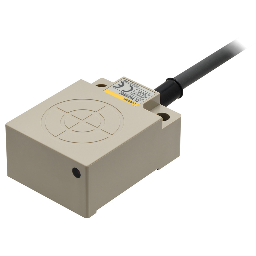
Flat Inductive Proximity Sensor
Image
Flat Inductive Proximity Sensor, Sensing distance: 20 mm, Unshielded, DC 3-wire, NPN, NC, Cable length 2 m
| Sensing head size |
40 mm x 23 mm x 53 mm |
|---|---|
| Type |
Square type, Unshielded |
| Power source |
DC Three-wires models |
| Sensing distance |
20 mm ±10% |
| Setting distance |
0 to 16 mm |
| Operation mode |
NC |
- Ratings/Performance
As of August 8, 2024
| Sensing head size | 40 mm x 23 mm x 53 mm |
|---|---|
| Type | Square type, Unshielded |
| Power source | DC Three-wires models |
| Sensing distance | 20 mm ±10% |
| Setting distance | 0 to 16 mm |
| Differential distance | 1% to 15% of sensing distance |
| Sensing object | Ferrous metal (Sensitivity lowers with non-ferrous metals.) |
| Standard sensing object | Iron 50 x 50 x 1 mm |
| Response frequency | 40 Hz (Average value) |
| Power supply voltage | 12 to 24 VDC ripple (p-p) 10% max. |
| Operating voltage range | 10 to 30 VDC |
| Current consumption | at 24 VDC, no load: 15 mA max. at 12 VDC, no load: 8 mA max. |
| Control output (Output type) | NPN |
| Control output (Switching capacity) | at 12 VDC: 100 mA max. at 24 VDC: 200 mA max. |
| Control output (Residual voltage) | 1 V max. (Load current 200 mA with cable length of 2 m) |
| Indicator | Detection indicator (red) |
| Operation mode | NC |
| Protective circuit | Reverse polarity protection Surge suppressor |
| Ambient temperature (Operating) | -25 to 70 ℃ |
| Ambient temperature (Storage) | -25 to 70 ℃ |
| Ambient humidity (Operating) | 35 to 95 % |
| Ambient humidity (Storage) | 35 to 95 % |
| Temperature influence | ±10% max. of sensing distance at 23 ℃ in the temperature range of -25 to 70 ℃ |
| Voltage influence | ±2.5% max. of sensing distance at rated voltage in the rated voltage ±10% range |
| Insulation resistance | Between charged parts and the case: 50 MΩ min. at 500 VDC |
| Dielectric strength | Between charged parts and the case: 1,000 VAC 50/60 Hz 1 min |
| Vibration resistance | Destruction: 10 to 55 Hz, 1.5 mm double amplitude each in X, Y, and Z directions for 2 h |
| Shock resistance | Destruction: 500 m/s2 10 times each in X, Y, and Z directions |
| Degree of protection | IEC: IP67 Company standard: Oil-proof |
| Connection method | Pre-wired models (2 m) |
| Weight | Package: Approx. 210 g |
| Material | Case: Heat-resistant ABS resin Sensing surface: Heat-resistant ABS resin |
| Accessories | Instruction manual |
As of August 8, 2024
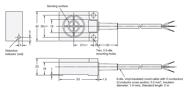
- Dimensions
As of August 8, 2024
Dimensions
As of August 8, 2024
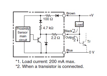
- Output circuit
As of August 8, 2024
Output circuit
Timing chart
As of August 8, 2024
- Mutual interference
As of August 8, 2024
Mutual interference
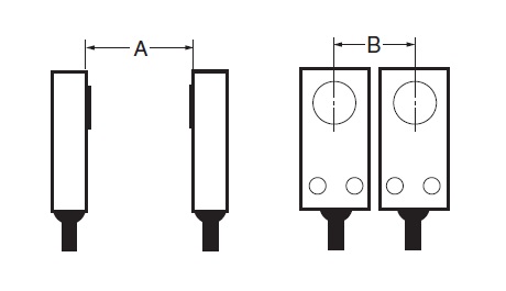
A: 200 mm min., B: 200 mm min.
As of August 8, 2024
- Effects of surrounding metals
As of August 8, 2024
Effects of surrounding metals

l: 25 mm min., m: 16 mm min., n: 100 mm min.
As of August 8, 2024
- Characteristic chart
As of August 8, 2024
Sensing distance vs. size and material of sensing object
Sensing range
As of August 8, 2024

© Copyright OMRON Corporation 2007 - 2021. All Rights Reserved.