Photoelectric Sensors
Photoelectric Sensors detect photo-optical workpieces. OMRON provides many varieties of Sensor, including diffuse-reflective, through-beam, retro-reflective, and distance-settable Sensors, as well as Sensors with either built-in or separate amplifiers and Fiber Units.
| Introduction |
|
|
|
|
|
|
|
|
|
Troubleshooting |
What Is a Photoelectric Sensor?
Photoelectric Sensors detect objects, changes in surface conditions, and other items through a variety of optical properties.
A Photoelectric Sensor consists primarily of an Emitter for emitting light and a Receiver for receiving light. When emitted light is interrupted or reflected by the sensing object, it changes the amount of light that arrives at the Receiver. The Receiver detects this change and converts it to an electrical output. The light source for the majority of Photoelectric Sensors is infrared or visible light (generally red, or green/blue for identifying colors).
Photoelectric Sensors are classified as shown in the figure below. (See Classification.)
Through-beam Sensors
Retro-reflective Sensors

Diffuse-reflective Sensors

Features
1. Long Sensing Distance
A Through-beam Sensor, for example, can detect objects more than 10 m away. This is impossible with magnetic, ultrasonic, or other sensing methods.
2. Virtually No Sensing Object Restrictions
These Sensors operate on the principle that an object interrupts or reflects light, so they are not limited like Proximity Sensors to detecting metal objects. This means they can be used to detect virtually any object, including glass, plastic, wood, and liquid.
3. Fast Response Time
The response time is extremely fast because light travels at high speed and the Sensor performs no mechanical operations because all circuits are comprised of electronic components.
4. High Resolution
The incredibly high resolution achieved with these Sensors derives from advanced design technologies that yielded a very small spot beam and a unique optical system for receiving light. These developments enable detecting very small objects, as well as precise position detection.
5. Non-contact Sensing
There is little chance of damaging sensing objects or Sensors because objects can be detected without physical contact.
This ensures years of Sensor service.
6. Color Identification
The rate at which an object reflects or absorbs light depends on both the wavelength of the emitted light and the color of the object. This property can be used to detect colors.
7. Easy Adjustment
Positioning the beam on an object is simple with models that emit visible light because the beam is visible.
Operating Principles
(1) Properties of Light
Rectilinear Propagation
When light travels through air or water, it always travels in a straight line. The slit on the outside of a Through-beam Sensor that is used to detect small objects is an example of how this principle is applied to practical use.

Refraction
Refraction is the phenomenon of light being deflected as it passes obliquely through the boundary between two media with different refractive indices.

Reflection
(Regular Reflection, Retroreflection, Diffuse Reflection)
A flat surface, such as glass or a mirror, reflects light at an angle equal to the incident angle of the light. This kind of reflection is called regular reflection. A corner cube takes advantage of this principle by arranging three flat surfaces perpendicular to each other. Light emitted toward a corner cube repeatedly propagates regular reflections and the reflected light ultimately moves straight back toward the emitted light. This is referred to as retroreflection.
Most retroreflectors are comprised of corner cubes that measure several square millimeters and are arranged in a precise configuration.
Matte surfaces, such as white paper, reflect light in all directions. This scattering of light is called diffuse reflection.
This principle is the sensing method used by Diffuse-reflective Sensors.

Polarization of Light
Light can be represented as a wave that oscillates horizontally and vertically. Photoelectric Sensors almost always use LEDs as the light source. The light emitted from LEDs oscillates in the vertical and horizontal directions and is referred to as unpolarized light. There are optical filters that constrain the oscillations of unpolarized light to just one direction. These are known as polarizing filters. Light from an LED that passes through a polarizing filter oscillates in only one direction and is referred to as polarized light (or more precisely, linear polarized light). Polarized light oscillating in one direction (say the vertical direction) cannot pass through a polarizing filter that constrains oscillations to a perpendicular direction (e.g., the horizontal direction). The MSR function on Retro-reflective Sensors and the Mutual Interference Protection Filter accessory for Through-beam Sensors operate on this principle.
(2) Light Sources
Light Generation
Pulse Modulated light
The majority of Photoelectric Sensors use pulse modulated light that basically emits light repeatedly at fixed intervals.
They can sense objects located some distance away because the effects of external light interference are easily removed with this system. In models equipped with mutual interference protection, the emission cycle is varied within a specified range to handle coherent light and external light interference.
Non-modulated Light
Non-modulated light refers to an uninterrupted beam of light at a specific intensity that is used with certain types of Sensors, such as Mark Sensors. Although these Sensors have fast response times, their drawbacks include short sensing distances and susceptibility to external light interference.

Light Source Color and Type
(3) Triangulation
Distance-settable Sensors generally operate on the principle of triangulation. This principle is illustrated in the following diagram.
Light from the Emitter strikes the sensing object and reflects diffused light. The Receiver lens concentrates the reflected light on the position detector (a semiconductor that outputs a signal according to where the light strikes it). When the sensing object is located at A near the optical system, then the light is concentrated at point a on the position detector. When the sensing object is located at B away from the optical system, then the light is concentrated at point b on the position detector.

Classification
(1) Classification by Sensing Method
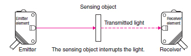
1. Through-beam Sensors
Sensing Method
The Emitter and Receiver are installed opposite each other to enable the light from the Emitter to enter the Receiver. When a sensing object passing between the Emitter and Receiver interrupts the emitted light, it reduces the amount of light that enters the Receiver. This reduction in light intensity is used to detect an object.

The sensing method is identical to that of Through-beam Sensors and some models called Slot Sensors are configured with an integrated Emitter and Receiver.

Features
Stable operation and long sensing distances ranging from several centimeters to several tens of meters.
Sensing position unaffected by changes in the sensing object path.
Operation not greatly affected by sensing object gloss, color, or inclination.
2. Diffuse-reflective Sensors
Sensing Method
The Emitter and Receiver are installed in the same housing and light normally does not return to the Receiver. When light from the Emitter strikes the sensing object, the object reflects the light and it enters the Receiver where the intensity of light is increased. This increase in light intensity is used to detect the object.

Features
Sensing distance ranging from several centimeters to several meters.
Easy mounting adjustment.
The intensity of reflected light, operating stability, and sensing distance vary with the conditions (e.g., color and smoothness) on the surface of the sensing object.
3. Retro-reflective Sensors
Sensing Method
The Emitter and Receiver are installed in the same housing and light from the Emitter is normally reflected back to the Receiver by a Reflector installed on the opposite side. When the sensing object interrupts the light, it reduces the amount of light received. This reduction in light intensity is used to detect the object.

Features
Sensing distance ranges from several centimeters to several meters.
Simple wiring and optical axis adjustment (labor saving).
Operation not greatly affected by the color or angle of sensing objects.
Light passes through the sensing object twice, making these Sensors suitable for sensing transparent objects.
Sensing objects with a mirrored finish may not be detected because the amount of light reflected back to the Receiver from such shiny surfaces makes it appear as though no sensing object is present. This problem can be overcome using the MSR function.
Retro-reflective Sensors have a dead zone at close distances.
4. Distance-settable Sensors
Sensing Method
The Receiver in the Sensor is either a 2-part photodiode or a position detector. The light reflected from the sensing object is concentrated on the Receiver. Sensing is based on the principle of triangulation, which states that where the beam is concentrated depends on the distance to the sensing object.
The following figure shows a detection system that uses a 2-part photodiode. The end of the photodiode nearest the case is called the N (near) end and the other end is called the F (far) end. When a sensing object reaches the preset position, the reflected light is concentrated midway between the N end and the F end and the photodiodes at both ends receive an equal amount of light. If the sensing object is closer to the Sensor, then the reflected light is concentrated at the N end. Conversely, the reflected light is concentrated at the F end when the sensing object is located farther than the preset distance. The Sensor calculates the difference between the light intensity at the N end and F end to determine the position of the sensing object.

Features
Operation not greatly affected by sensing object surface conditions or color.
Operation not greatly affected by the background.
BGS (Background Suppression) and FGS (Foreground Suppression)
When using the E3Z-LS61, E3Z-LS66, E3Z-LS81, or E3Z-LS86, select the BGS or FGS function to detect objects on a conveyor belt.
The BGS function prevents any background object (i.e., the conveyor) beyond the set distance from being detected.
The FGS function prevents objects closer than the set distance or objects that reflect less than a specified amount of light to the Receiver from being detected.
Objects that reflect less than a specified amount of light are as follows:
(1) Objects with extremely low reflectance and objects that are darker than black paper.
(2) Objects like mirrors that return virtually all light back to the Emitter.
(3) Uneven, glossy surfaces that reflect a lot of light but disperse the light in random directions.
Reflected light may return to the Receiver momentarily for item (3) due to sensing object movement. In that case, an OFF delay timer or some other means may need to be employed to prevent chattering.
Features
Small differences in height can be detected (BGS and FGS).
The effects of sensing object color are minimized (BGS and FGS).
The effects of background objects are minimized (BGS).
Sensing object irregularities may affect operation (BGS and FGS).


5. Limited-reflective Sensors
Sensing Method
In the same way as for Diffuse-reflective Sensors, Limited-reflective Sensors receive light reflected from the sensing object to detect it. The optical system restricts the light emission and reception area, so only objects that are a specific distance (area where light emission and reception overlap) from the Sensor can be detected. In the figure on the right, the sensing object at (A) can be detected while the object at (B) cannot.
Example
Features
Small differences in height can be detected.
The distance from the Sensor can be limited to detect only objects in a specific area.
Operation is not greatly affected by sensing object colors.
Operation is greatly affected by the glossiness or inclination of the sensing object.
(2) Selection Points by Sensing Method
Checkpoints for Through-beam and Retro-reflective Sensors
Sensing object
(1) Size and shape (vertical x horizontal x height)
(2) Transparency (opaque, semi-transparent, transparent)
(3) Velocity V (m/s or units/min.)
Sensor
(1) Sensing distance (L)
(2) Restrictions on size and shape
a) Sensor
b) Retroreflector (for Retro-reflective Sensors)
(3) Need for side-by-side mounting
a) No. of units
b) Mounting pitch
c) Need for staggered mounting
(4) Mounting restrictions (angling, etc.)
Environment
(1) Ambient temperature
(2) Presence of splashing water, oil, or chemicals
(3) Others
Checkpoints for Diffusion-reflective, Distance-settable, and Limited-reflective Sensors
Sensing object
(1) Size and shape (vertical x horizontal x height)
(2) Color
(3) Material (steel, SUS, wood, paper, etc.)
(4) Surface conditions (textured or glossy)
(5) Velocity V (m/s or units/min.)
Sensor
(1) Sensing distance (distance to the workpiece) (L)
(2) Restrictions on size and shape
(3) Need for side-by-side mounting
a) No. of units
b) Mounting pitch
(4) Mounting restrictions (angling, etc.)
Background
Background
(1) Color
(2) Material (steel, SUS, wood, paper, etc.)
(3) Surface conditions (textured, glossy, etc.)
Environment
(1) Ambient temperature
(2) Presence of splashing water, oil, or chemicals
(3) Others

(3) Classification by Configuration
Photoelectric Sensors are generally comprised of an Emitter, Receiver, Amplifier, Controller, and Power Supply. They are classified as shown below according to how the components are configured.
1. Sensors with Separate Amplifiers
Through-beam Sensors have a separate Emitter and Receiver while Reflective Sensors have an integrated Emitter and Receiver. The Amplifier and Controller are housed in a single Amplifier Unit.
Features
Compact size because the integrated Emitter-Receiver is comprised simply of an Emitter, Receiver, and optical system.
Sensitivity can be adjusted remotely if the Emitter and Receiver are installed in a narrow space.
The signal wire from the Amplifier Unit to the Emitter and Receiver is susceptible to noise.
Typical Models (Amplifier Units): E3NC, E3C-LDA[]N, and E3C
2. Built-in Amplifier Sensors
Everything except the power supply is integrated in these Sensors. (Through-beam Sensors are divided into the Emitter comprised solely of the Emitter and the Receiver comprised of the Receiver, Amplifier, and Controller.) The power supply is a standalone unit.
Features
The Receiver, Amplifier, and Controller are integrated to eliminate the need for weak signal wiring. This makes the Sensor less susceptible to noise.
Requires less wiring than Sensors with separate Amplifiers.
Although these Sensors are generally larger than those with separate Amplifiers, those with non-adjustable sensitivity are just as small.
Typical Models: E3Z, E3T, and E3S-C
3. Sensors with Built-in Power Supplies
The Power Supply, Emitter, and Receiver are all installed in the same housing with these Sensors.
Features
Sensors can be connected directly to a commercial power supply to provide a large control output directly from the Receiver.
These Sensors are much larger than those with other configurations because the Emitter and Receiver contain additional components, such as power supply transformers.
Typical Models: E3G-M, E3JK, and E3JM
4. Area Sensors
An Area Sensor is a Through-beam Sensor which consists of a pair of Emitter and Receiver with multiple beams. Select the sensing width of the Sensor to fit the application.
Features
Area Sensors can sense wide areas.
These Sensors are ideal for picking systems for small parts.
Typical Models: F3W-E and F3W-D