E5AC-QX2ASM-009
Digital Temperature Controller (96 x 96 mm)
Image
Digital Temperature Controller, 96 x 96 mm, Voltage output (for driving SSR), Auxiliary output: 2, Power supply voltage: 100 to 240 VAC, Universal inputs, HB alarm and HS alarm: 2, RS-485, 2 event inputs, Screw terminal block model
| Shape |
DIN 96 x 96 |
|---|---|
| Terminal type |
Screw terminal block |
| Input type |
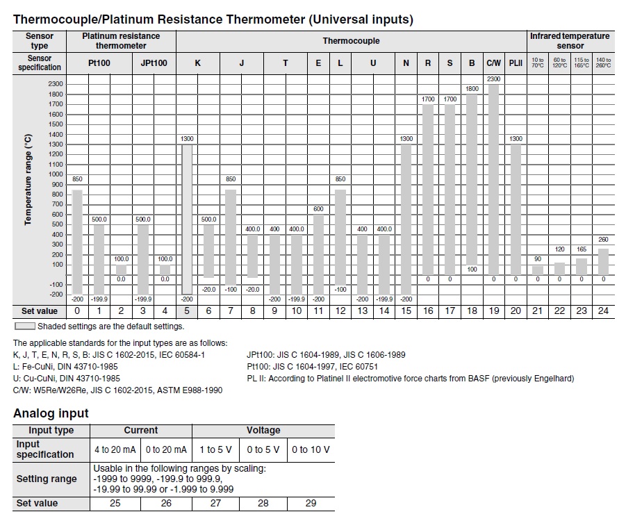
Thermocouple/Platinum resistance thermometer/Infrared Thermosensor/Analog input |
| Control output 1 |
Voltage output (for driving SSR) |
| Control output 2 |
None |
| Number of total auxiliary output |
2 point |
| Power supply voltage |
100 to 240 VAC (50/60 Hz) |
| Number of event input |
2 point |
| Heater burnout /SSR failure detector |
2 points |
| Communications method |
RS-485 (two-wire, half duplex) |
- Ratings / Performance
As of November 4, 2025
| Shape | DIN 96 x 96 | |
|---|---|---|
| Fixed/Programmable | Fixed | |
| Power supply voltage | 100 to 240 VAC (50/60 Hz) | |
| Allowable voltage variable range | 85 to 110% of the power supply voltage | |
| Power consumption | 9 VA max. (at 100 to 240 VAC) | |
| Input | Number of input points | 1 point | Temperature input | Thermocouple: K, J, T, E, L, U, N, R, S, B, C/W, PLII Platinum resistance thermometer: Pt100, JPt100 Infrared Thermosensor: 10 to 70 ℃, 60 to 120 ℃, 115 to 165 ℃, 140 to 260 ℃ | Analog input | 4 to 20 mA or 0 to 20 mA | Input impedance | Current input: 150 Ω max., voltage input: 1 MΩ min. (Applicable when connecting 1:1 to ES2-HB-N/THB-N.) |
| Control method | ON/OFF control or 2-PID control (with auto-tuning) | |
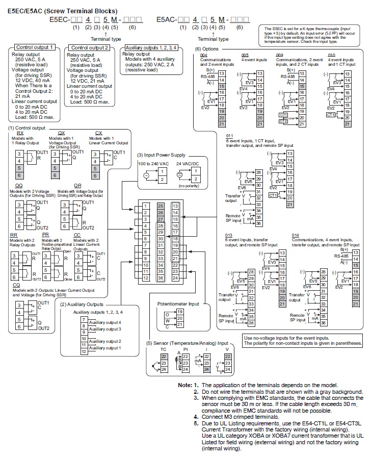
| Control output | Number of total control output | 1 point | Control output 1 | Voltage output (for driving SSR) | Control output 2 | None | Voltage output (for driving SSR) | 1 point 12 VDC±20%, Maximum load current: 40 mA, PNP, with short-circuit protection circuit |
| Auxiliary output | Number of total auxiliary output | 2 point | Relay output | SPST-NO, 250 VAC, 3 A (resistive load), electrical life: 100,000 operations (minimum applicable load: 5 V, 10 mA) |
| Event input | 2 point Contact input: ON: 1 kΩ max., OFF: 100 kΩ min. No-contact input: ON: Residual voltage 1.5 V max., OFF: Leakage current 0.1 mA max. Current flow: Approx. 7 mA per point | |
| Setting method | Digital setting using front panel keys | |
| Indication method | 11-segment digital display and individual indicators | |
| Multi SP functions | Up to eight set points (SP0 to SP7) can be saved and selected using the event inputs, key operations, or serial communications. | |
| Sampling period | 50 ms | |
| Hysteresis | Temperature input: 0.1 to 999.9 ℃ or °F (in units of 0.1 ℃ or °F) Analog input: 0.01 to 99.99% FS (in units of 0.01% FS) | |
| Proportional band | Temperature input: 0.1 to 999.9 ℃ or °F (in units of 0.1 ℃ or °F) Analog input: 0.1% to 999.9% FS (in units of 0.1% FS) | |
| Integral time | 0 to 9999 s (in units of 1 s), 0.0 to 999.9 s (in units of 0.1 s) | |
| Derivative time | 0 to 9999 s (in units of 1 s), 0.0 to 999.9 s (in units of 0.1 s) | |
| for cooling | Proportional band (P) | Temperature input: 0.1 to 999.9 ℃ or °F (in units of 0.1 ℃ or °F) Analog input: 0.1% to 999.9% FS (in units of 0.1% FS) | Integral time (I) | 0 to 9999 s (in units of 1 s), 0.0 to 999.9 s (in units of 0.1 s) | Derivative time (D) | 0 to 9999 s (in units of 1 s), 0.0 to 999.9 s (in units of 0.1 s) |
| Control period | 0.1 s, 0.2 s, 0.5 s, 1 to 99 s (in units of 1 s) | |
| Manual reset value | 0.0 to 100.0% (in units of 0.1%) | |
| Insulation resistance | 20 MΩ min. (at 500 VDC) | |
| Dielectric strength | 3,000 VAC 50/60 Hz 1 min (Between current-carrying terminals of different polarity) | |
| Vibration resistance | Destruction: 10 to 55 Hz, 20 m/s2 for 2 h each in X, Y, and Z directions Malfunction: 10 to 55 Hz, 20 m/s2 for 10 min each in X, Y, and Z directions | |
| Shock resistance | Destruction: 300 m/s2, 3 times each in X, Y, and Z directions Malfunction: 100 m/s2, 3 times each in X, Y, and Z directions | |
| Ambient temperature (Operating) | -10 to 55 ℃ (with no freezing or condensation) For 3-year warranty with standard mounting: -10 to 50 ℃ (with no freezing or condensation) | |
| Ambient temperature (Storage) | -25 to 65 ℃ (with no freezing or condensation) | |
| Ambient humidity (Operating) | 25 to 85 % | |
| Altitude | 2000 m max. | |
| Degree of protection | Front panel: IP66, Rear case: IP20, Terminal section: IP00 | |
| Memory protection | Non-volatile memory (number of writes: 1,000,000) | |
| Case color | Black | |
| Terminal type | Screw terminal block | |
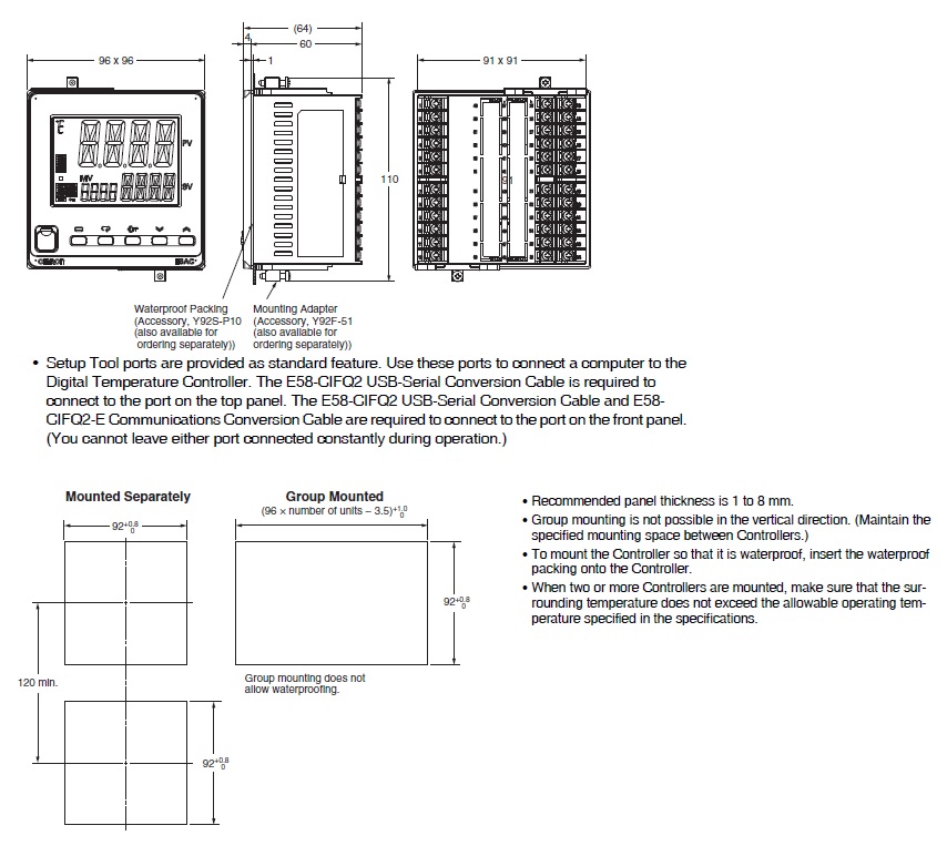
| Accessories | Mounting adapter, Waterproof packing, Front Port Cover | |
| Weight | Main Unit: Approx. 250 g Adapter: Approx. 4 g x 2 | |
| Sold separately | USB Serial Conversion Cable: E58-CIFQ2 Communications Conversion Cable: E58-CIFQ2-E Terminal Cover: E53-COV24 Waterproof packing: Y92S-P10 Waterproof Cover: Y92A-96N Front Port Cover: Y92S-P7 Adapter: Y92F-51 CX-Thermo Support Software: EST2-2C-MV4 Current Transformer (CT): E54-CT1/E54-CT1L/E54-CT3/E54-CT3L | |
| Indication accuracy | Thermocouple: (±0.3% of indicated value or ±1 ℃, whichever is greater) ±1 digit max. Platinum resistance thermometer: (±0.2% of indicated value or ±0.8 ℃, whichever is greater) ±1 digit max. Analog input: ±0.2% FS ±1 digit max. (The indication accuracy of K thermocouples in the -200 to 1300 ℃ range, T and N thermocouples at a temperature of -100 ℃ max., and U and L thermocouples at any temperatures is ±2 ℃ ±1 digit max. B thermocouple at a temperature of 400 ℃ max. is not specified. B thermocouples in the 400 to 800 ℃ range is ±3 ℃ max. R and S thermocouples at a temperature of 200 ℃ max. is ±3 ℃ ±1 digit max. C/W thermocouples is (±0.3% PV or ±3 ℃, whichever is greater) ±1 digit max. PL II thermocouples is (±0.3% PV or ±2 ℃, whichever is greater) ±1 digit max.) |
|---|---|
| Influence of temperature/voltage | Thermocouple: R, S, B, C/W, and PLII: (±1% of indicated value or ±10 ℃, whichever is greater) ±1 digit max. Other thermocouple: (±1% of indicated value or ±4 ℃, whichever is greater) ±1 digit max.. However K thermocouple at -100 ℃ max.: ±10 ℃ max. Platinum resistance thermometer: (±1% of indication value or ±2 ℃, whichever is greater) ±1 digit max. Analog input: ±1% FS ±1 digit max. CT input: ±5% FS ±1 digit max. Ambient temperature: -10 to 23 to 55 ℃, Voltage range: -15 to 10% of rated voltage |
| Influence of EMS. | Thermocouple: R, S, B, C/W, and PLII: (±1% of indicated value or ±10 ℃, whichever is greater) ±1 digit max. Other thermocouple: (±1% of indicated value or ±4 ℃, whichever is greater) ±1 digit max.. However K thermocouple at -100 ℃ max.: ±10 ℃ max. Platinum resistance thermometer: (±1% of indication value or ±2 ℃, whichever is greater) ±1 digit max. Analog input: ±1% FS ±1 digit max. |
| Influence of signal source resistance | Thermocouple: 0.1℃/Ω max. (100 Ω max.) Platinum resistance thermometer: 0.1℃/Ω max. (10 Ω max.) |
| Transmission path connection | Multidrop (RS-485) |
|---|---|
| Communications method | RS-485 (two-wire, half duplex) |
| Synchronization method | Start-stop synchronization |
| Protocol | CompoWay/F, Modbus |
| Communication speed | 9600, 19200, 38400, 57600 bps |
| Transmission code | ASCII |
| Data bit length | 7 or 8 bits |
| Stop bit length | 1 or 2 bits |
| Error detection | Vertical parity (none, even, odd) Block check character (BCC) with CompoWay/F CRC-16 Modbus |
| Flow control | None |
| Interface | RS-485 |
| Retry function | None |
| Communications buffer | 217 bytes |
| Communications response send delay | 0 to 99 ms (Default: 20 ms) |
| Programless communications function | You can use the memory in the PLC to read and write E5□C parameters, start and stop operation, etc. The E5□C automatically performs communications with PLCs. No communications programming is required. Number of connected Digital Temperature Controllers: 32 max. (Up to 16 for the FX Series) |
|---|---|
| Component communications | When Digital Temperature Controllers are connected, set points and RUN/STOP commands can be sent from the Digital Temperature Controller that is set as the master to the Digital Temperature Controllers that are set as slaves. Slope and offsets can be set for the set point. Number of connected Digital Temperature Controllers: 32 max. (including master) |
| Copying | When Digital Temperature Controllers are connected, the parameters can be copied from the Digital Temperature Controller that is set as the master to the Digital Temperature Controllers that are set as slaves. |
| CT input (for heater current detection) | 2 points |
|---|---|
| Max. heater current | Single-phase or Three-phase 50 A AC |
| Input current indication accuracy | ±5% FS ±1 digit max. |
| Heater burnout alarm setting range | 0.1 to 49.9 A (in units of 0.1 A) Minimum detection ON time: 100 ms (The value is 30 ms for a control period of 0.1 s or 0.2 s) |
| SSR failure detector alarm setting range | 0.1 to 49.9 A (in units of 0.1 A) Minimum detection OFF time: 100 ms (The value is 35 ms for a control period of 0.1 s or 0.2 s) |
As of November 4, 2025
- Dimensions
As of November 4, 2025
As of November 4, 2025
- Connection diagram
As of November 4, 2025
As of November 4, 2025
- Input ranges list
As of November 4, 2025
As of November 4, 2025

© Copyright OMRON Corporation 2007 - 2021. All Rights Reserved.