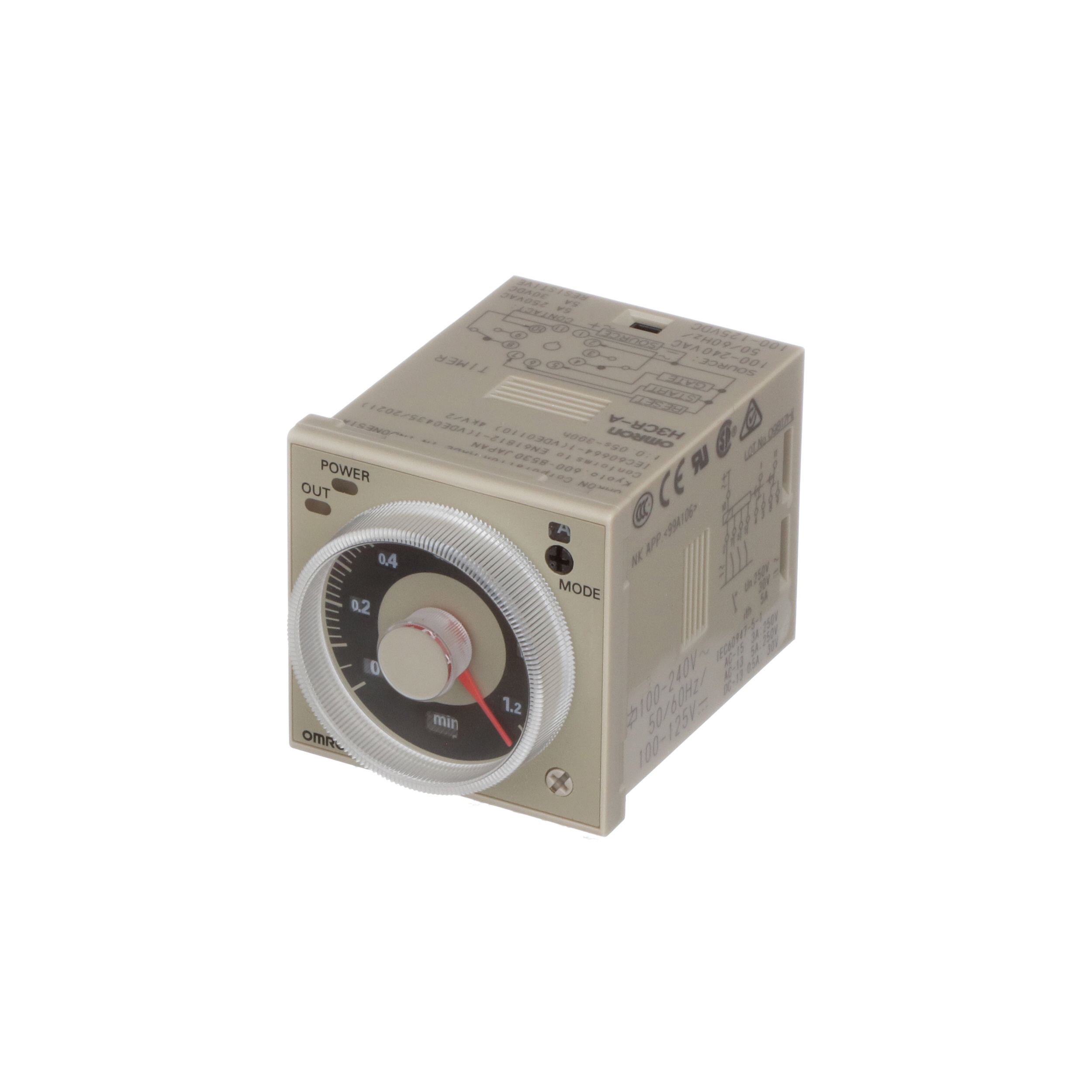
H3CR-AP AC24-48/DC12-48
Solid-state Multi-functional Timers
Image
Solid-state Timer, 11-pin, Time range: 0.05 s to 300 h, Voltage input (PNP), Relay output (DPDT) Time-limit contact, 24 to 48 VAC/12 to 48 VDC
| Rated power supply voltage |
24 to 48 VAC 50/60 Hz 12 to 48 VDC Ripple 20% max. (If power supply incorporates a single-phase full-wave rectifier) |
|---|---|
| Input signals |
Start |
| Input method |
Voltage input |
| Control output (Type) |
Time-limit: DPDT |
| Operating resetting |
Time-limit operation/Self-reset |
| Connecting method |
11-pin round socket |
- Ratings/Specifications
As of December 23, 2024
| Rated power supply voltage | 24 to 48 VAC 50/60 Hz 12 to 48 VDC Ripple 20% max. (If power supply incorporates a single-phase full-wave rectifier) |
|---|---|
| Allowable voltage variable range | 85 to 110% of rated voltage (90 to 110% at 12 to 48 VDC) |
| Input signals | Start |
| Input method | Voltage input |
| Voltage input | High level: 20.4 to 52.8 VAC/10.8 to 52.8 VDC Low level: 0 to 2.4 VAC/0 to 1.2 VDC |
| Power consumption | Relay ON: Approx. 0.9 W (at 24 VDC)/Relay OFF: Approx. 0.3 W (at 24 VDC) |
| Reset voltage | 10% max. of rated supply voltage |
| Number of time ranges | 18 |
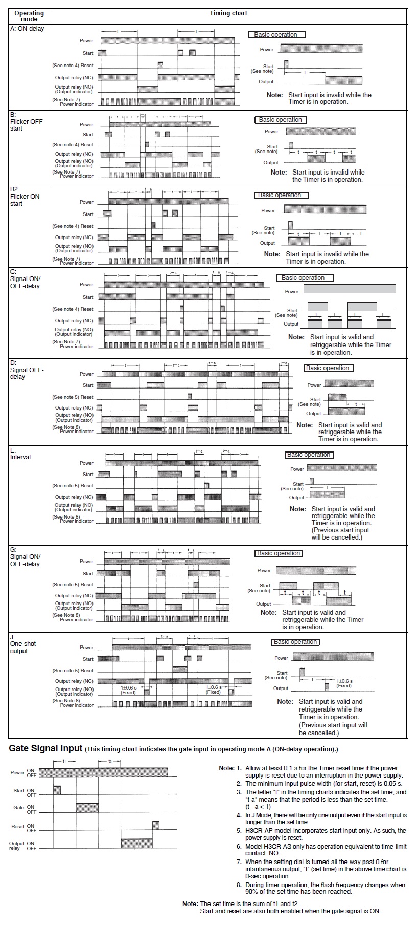
| Operation mode | ON delay, Flicker OFF start, Flicker ON start, Signal ON/OFF delay, Signal OFF delay, Interval, Signal ON/OFF delay, One shot output |
| Control output (Type) | Time-limit: DPDT |
| Control output (Contact output) | Resistive load: 250 VAC 5 A (cosφ=1)/5 A at 30 VDC/0.15 A at 125 VDC Inductive load (Reference value): 2 A at 250 VAC (cosφ=0.4)/3 A at 30 VDC (L/R=7 ms) Minimum applicable load: 10 mA at 5 VDC (failure level: P Reference value) |
| Operating resetting | Time-limit operation/Self-reset |
| Ambient temperature range | Operating: -10 to 55 ℃ (with no icing) Storage: -25 to 65 ℃ (with no icing) |
| Ambient humidity range | Operating: 35 to 85 % |
| Accuracy of operating time | ±0.2% FS max. ±0.2% ±10 ms in a range of 1.2 s and 3 s |
| Setting error | ±5% FS ±50 ms max. The value is ±5% FS +100 ms to -0 ms max. when the C, D, or G mode signal |
| Reset time | 0.1 s max. |
| Influence of voltage | ±0.2% FS max. ±0.2% ±10 ms in a range of 1.2 s and 3 s |
| Influence of temperature | ±1% FS max. (±1% ±10 ms in a range of 1.2 s and 3 s) |
| Insulation resistance | 100 MΩ min. (at 500 VDC) |
| Dielectric strength | Between current carrying metal parts and non-current carrying metal parts: 2,000 VAC 50/60 Hz 1 min Between control output terminals and operating circuit: 2,000 VAC 50/60 Hz 1 min Between contacts of different polarity: 2,000 VAC 50/60 Hz 1 min Between non-continuous contacts: 1,000 VAC 50/60 Hz 1 min Between input and control output/operation circuit: 2,000 VAC 50/60 Hz 1 min |
| Impulse withstand voltage | Between power terminals: 1 kV Between current carrying terminals and exposed non-current carrying metal parts: 1.5 kV |
| Noise immunity | ±1.5 kV (between power terminals), square-wave noise by noise simulator (pulse width: 100 ns/1 µs, 1-ns rise) |
| Static immunity | Mulfunction: 8 kV, Destruction: 15 kV |
| Vibration resistance | Destruction: 10 to 55 Hz, 0.75 mm single amplitude each in 3 directions for 2 h Malfunction: 10 to 55 Hz, 0.5 mm single amplitude each in 3 directions for 10 min |
| Shock resistance | Destruction: 1,000 m/s2, 3 times each in 6 directions Malfunction: 100 m/s2, 3 times each in 6 directions |
| Life expectancy (relay output) | Electrical: 100,000 operations min. (5 A at 250 VAC, resistive load at 1800 operations/h) Mechanical: 20 million operations min. (under no load at 1,800 operations/h) |
| Degree of protection | Panel surface: IP40 Terminals: IP00 |
| Connecting method | 11-pin round socket |
| Case color | Munsell 5Y7/1 |
| Weight | Approx. 90 g |
| Accessories | Instruction manual, Compliance information sheet |
| Applicable socket | P2CF-11/ P2CF-11-E/ P3GA-11/ PL11/ PL11-Q/ PLE11-0 |
As of December 23, 2024
- Dimensions
As of December 23, 2024
Outline drawing
As of December 23, 2024
- Internal connection
As of December 23, 2024
Internal connection
As of December 23, 2024
- Terminal arrangement
As of December 23, 2024
Terminal arrangement
As of December 23, 2024
- Input connections
As of December 23, 2024
Input connections
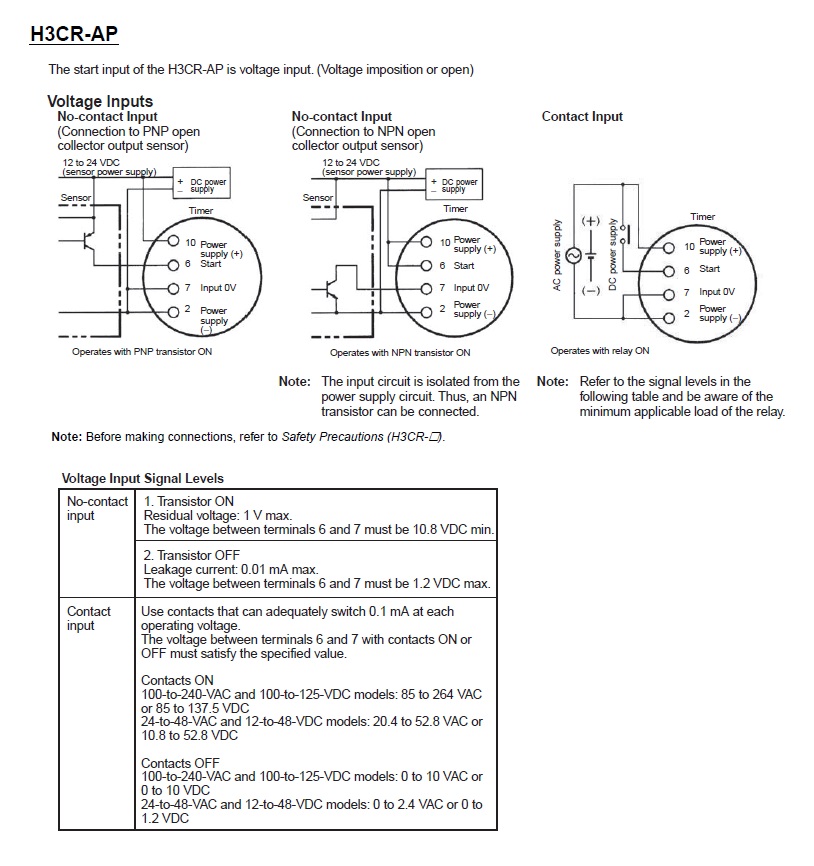
As of December 23, 2024
- Time ranges
As of December 23, 2024
Time ranges
As of December 23, 2024
- Operating chart
As of December 23, 2024
Operating chart
As of December 23, 2024
- Electrical life curve
As of December 23, 2024
Electrical life curve
As of December 23, 2024

© Copyright OMRON Corporation 2007 - 2021. All Rights Reserved.