H3FA-SAU DC5/6
Solid-state Timer

Image
Solid-state Timer, No-Contact output (SPST-NO + SPST-NC), Time range: 1 s to 10 min, Instantaneous operation, time-limit resetting/external resetting, 5/6 VDC
| Rated power supply voltage |
5/6 VDC Ripple 3% max. |
|---|---|
| Control output (Type) |
Transistor output |
| Operating resetting |
Instantaneous operation, time-limit resetting/external resetting |
| Connecting method |
PCB terminal |
- Ratings/Specifications
As of July 25, 2024
| Rated power supply voltage | 5/6 VDC Ripple 3% max. |
|---|---|
| Allowable voltage variable range | for 5 VDC: 90 to 110% of the power supply voltage/for 6 VDC: 85 to 110% of the power supply voltage |
| Power consumption | Approx. 80 mW |
| Number of time ranges | 4 |
| Operation mode | One shot output, Signal OFF delay |
| Control output (Type) | Transistor output |
| Control output (No-contact output) | 150 mA max. at 30 VDC, ON residual voltage: 1.0 V max. |
| Operating resetting | Instantaneous operation, time-limit resetting/external resetting |
| Ambient temperature range | Operating: -10 to 55 ℃ (with no icing) Storage: -25 to 65 ℃ (with no icing) |
| Ambient humidity range | Operating: 35 to 85 % |
| Accuracy of operating time | ±0.5% FS max. (±0.5% ±10 ms in a range of 1 s) |
| Setting error | 0 to +30% FS max. (at 20 ℃, rated voltage) |
| Reset time | 10 ms max. |
| Influence of voltage | ±2% FS max. |
| Influence of temperature | ±5% FS max. (±5% ±10 ms in a range of 1 s) |
| Insulation resistance | 100 MΩ min. (at 500 VDC) |
| Dielectric strength | Between control output terminals and operating circuit: 1,500 VAC 50/60 Hz 1 min Between non-continuous contacts: 1,000 VAC 50/60 Hz 1 min |
| Vibration resistance | Destruction: 10 to 55 Hz, 0.375 mm single amplitude each in 3 directions for 2 h Malfunction: 10 to 55 Hz, 0.25 mm single amplitude each in 3 directions for 10 min |
| Shock resistance | Destruction: 1,000 m/s2, 3 times each in 6 directions Malfunction: 100 m/s2, 3 times each in 6 directions |
| Connecting method | PCB terminal |
| Weight | Approx. 10 g |
As of July 25, 2024
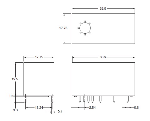
- Dimensions
As of July 25, 2024
Outline drawing

As of July 25, 2024
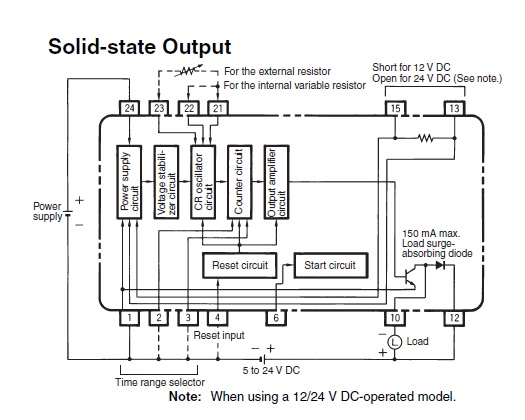
- Internal connection
As of July 25, 2024
Internal connection

As of July 25, 2024
- Time ranges
As of July 25, 2024
Time ranges

As of July 25, 2024
