K3HB-PNB-A-DRT1 AC100-240
Timer Interval Indicator
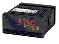
Image
Timer Interval Indicator, NPN input/voltage pulse input, Sensor power supply (12 VDC), DeviceNet, Event Input: 5 inputs (No-voltage contact/NPN), Terminal block type, 100 to 240 VAC
| Power supply voltage |
100 to 240 VAC 50/60 Hz |
|---|---|
| Input type |
Pulse (NPN/voltage pulse input) |
| Digits |
5 digit (-19999 to 99999) |
| Number of event input |
5 point |
- Ratings/Specifications
As of November 4, 2025
| Power supply voltage | 100 to 240 VAC 50/60 Hz | |
|---|---|---|
| Allowable power supply voltage range | 85 to 110% of the power supply voltage | |
| Power consumption | 18 VA max. (at maximum load) | |
| External power supply | 12 VDC ±10% 80 mA | |
| Input type | Pulse (NPN/voltage pulse input) | |
| Output type | Transfer output: DeviceNet | |
| Pulse measurement input | Function | F1: Passing speed F2: Cycle F3: Time difference F4: Time band F5: Measuring length F6: Interval | Contact input (dry contact input) | 30 Hz max. ON/OFF pulse width of 15 ms min. | No contact voltage pulse | F1 to F4: 0 to 50 kHz ON/OFF pulse width of 9 µs min. F5, F6: 0 to 30 kHz ON/OFF pulse width of 16 µs min. | Voltage level | ON voltage: 4.5 to 30 V, OFF voltage: -30 to 2 V, input impedance: 10 kΩ | Open collector | F1 to F4: 0 to 50 kHz ON/OFF pulse width of 9 µs min. F5, F6: 0 to 30 kHz ON/OFF pulse width of 16 µs min. | Measurement range | F1: 10 ms to 3200 s F2: 20 ms to 3200 s F3: 10 ms to 3200 s F4: 10 ms to 3200 s F5: 0 to 4 gigacounts F6: 0 to 4 gigacounts | Accuracy | ±0.08% rdg ±1 digit (23±5 ℃, for voltage pulse/open collector sensors) |
| Event input | Number of input | 5 point | Input method | NO-Voltage contact/NPN open collector | Event name | Hold input Reset input | Connection method | Terminal blocks | Contact | ON: 1 kΩ max. OFF: 100 kΩ min. | No-contact | ON residual voltage: 2 V max. OFF leakage current: 4 mA max. Maximum applied voltage: 30 V max.DC Leakage current: 0.1 mA max. |
| Display | Display method | Negative LCD (backlit LED) 7-segment digital display | Digits | 5 digit (-19999 to 99999) | Character height | PV: 14.2 mm (green/red) SV: 4.9 mm (green) |
| Insulation resistance | 20 MΩ min. (at 500 VDC) | |
| Dielectric strength | Between the entire external terminal and case: 2,300 VAC 1 min | |
| Noise immunity | ±1,500 V at power supply terminals in normal or common mode (waveform with 1-ns rising edge and pulse width of 1 µs/100 ns) | |
| Vibration resistance | Malfunction: 10 to 55 Hz, Acceleration: 50 m/s2, 5 min 10 sweeps each in X, Y, and Z directions | |
| Shock resistance | Malfunction: 150 m/s2, 3 times each in 3 axes 6 directions | |
| Degree of protection | Front: NEMA4X for indoor use (equivalent to IP66) Case rear: IP20 Terminals: IP00 + finger protection (VDE0106/100) | |
| Memory protection | EE-PROM (non-volatile memory) Number of rewrites: 100,000 | |
| Ambient temperature | Operating: -10 to 55 ℃ (with no freezing or condensation) Storage: -25 to 65 ℃ (with no freezing or condensation) | |
| Ambient humidity | Operating: 25 to 85 % | |
| Accessories | Waterproof packing, Fixtures, Terminal Cover, Unit label, Instruction manual, DeviceNet connector (made from Hirose), Crimp terminals (made from Hirose) | |
| Weight | Approx. 300 g | |
| Communications protocol | Conforms to DeviceNet |
|---|---|
| Remote IO communications | Master-Slave connection (Poll/Bit-Strobe/COS/Cyclic) Conforms to DeviceNet communications standards. |
| IO allocations | Allocate any I/O data using the Configurator. Allocate any datasuch as DeviceNet-specific parameters and variable area for Digital Indicators. Input area: 2 blocks 60 words max. Output area: 1 block 29 words max. (The first word in the area is always allocated for the Output Execution Enabled Flags.) |
| Message communications | Explicit message communications CompoWay/F communications commands can be executed (using explicit message communications) |
| Connection forma | Combination of multi-drop and T-branch connectors (for trunk and drop line) |
| Communications media | Special 5-wire cable (2 signal lines, 2 power supply lines, 1 shield line) |
| Current consumption | 50 mA max. (24 VDC) |
| Maximum number of nodes | 64 (DeviceNet Configurator is counted as one node when connected) |
| Maximum number of slaves | 63 |
| power supply | Supplied from DeviceNet communications connector |
| Power supply voltage | 24 VDC (11 to 25 VDC) |
As of November 4, 2025
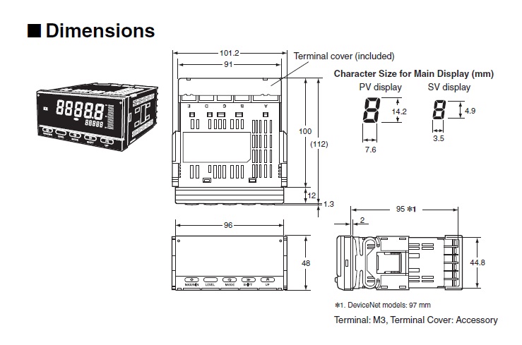
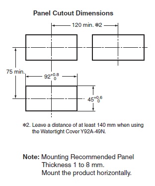
- Dimensions
As of November 4, 2025
As of November 4, 2025
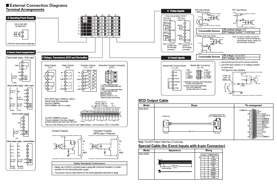
- Connection diagram
As of November 4, 2025
Terminal arrangement
As of November 4, 2025
- Internal connection
As of November 4, 2025
As of November 4, 2025

© Copyright OMRON Corporation 2007 - 2021. All Rights Reserved.