K3HB-RNB-ABCD2 AC100-240
Rotary Pulse Indicator
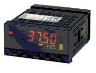
Image
Rotary Pulse Indicator, NPN input/voltage pulse input, Sensor power supply (12 VDC), BCD output + transistor output (No-voltage contact/NPN), Event Input: 8 inputs (No-voltage contact/NPN), Connector type, 100 to 240 VAC
| Power supply voltage |
100 to 240 VAC 50/60 Hz |
|---|---|
| Input type |
Pulse (NPN/voltage pulse input) |
| Digits |
5 digit (-19999 to 99999) |
| Number of event input |
8 point |
- Ratings/Specifications
As of July 25, 2024
| Power supply voltage | 100 to 240 VAC 50/60 Hz | |
|---|---|---|
| Allowable power supply voltage range | 85 to 110% of the power supply voltage | |
| Power consumption | 18 VA max. (at maximum load) | |
| External power supply | 12 VDC ±10% 80 mA | |
| Input type | Pulse (NPN/voltage pulse input) | |
| Output type | Judgment output: Transistor Comparative output: HH, H, PASS, L, LL Transfer output: BCD | |
| Pulse measurement input | Function | F1: Rpm/circumferenitial speed/Instantaneous flowrate F2: Absolute raito F3: Error raito F4: Accuracy F5: Flow rate ratio F6: Passing time | Contact input (dry contact input) | 30 Hz max. ON/OFF pulse width of 15 ms min. | No contact voltage pulse | 50 kHz max. ON/OFF pulse width of 9 µs min. | Voltage level | ON voltage: 4.5 to 30 V, OFF voltage: -30 to 2 V, input impedance: 10 kΩ | Open collector | 50 kHz max. ON/OFF pulse width of 9 µs min. | Measurement range | F1 to F6: 0.5 mHz to 50 kHz (for voltage pulse/open collector sensors) | Accuracy | F1, F6: ±0.006% rdg ±1 digit F2 to F5: ±0.02% rdg ±1 digit (23±5 ℃, for voltage pulse/open collector sensors) |
| Event input | Number of input | 8 point | Input method | NO-Voltage contact/NPN open collector | Event name | Startup compensation timer input Hold input Reset input Bank input | Connection method | Connector | Contact | ON: 1 kΩ max. OFF: 100 kΩ min. | No-contact | ON residual voltage: 2 V max. OFF leakage current: 4 mA max. Maximum applied voltage: 30 V max.DC Leakage current: 0.1 mA max. |
| BCD input | Input signal logic: Negative Input signal: No-voltage contact input (REQUEST/HOLD/MAX/MIN/RESET) Input current: 10 mA ON voltage: 1.5 V max. OFF voltage: 3 V min. | |
| BCD Output | Output signal name: DATA, POLARITY, OVER, DATA VALID, RUN/HH, H, PASS, L, LL Maximum load voltage: 24 V max.DC Maximum load current: 10 mA (DATA, POLARITY, OVER, DATA VALID, RUN)/50 mA (HH, H, PASS, L, LL) Leakage current: 100 µA max. | |
| Judgment output | Transistor output | NPN open collector Maximum load voltage: 24 V max.DC Maximum load current: 50 mA max. Leakage current: 100 µA max. |
| Display | Display method | Negative LCD (backlit LED) 7-segment digital display | Digits | 5 digit (-19999 to 99999) | Character height | PV: 14.2 mm (green/red) SV: 4.9 mm (green) |
| Comparative output response time | 100 ms max. (time until the comparative output is made when there is a forced sudden change in the input signal from 15% to 95% or 95% to 15%.) | |
| Insulation resistance | 20 MΩ min. (at 500 VDC) | |
| Dielectric strength | Between the entire external terminal and case: 2,300 VAC 1 min | |
| Noise immunity | ±1,500 V at power supply terminals in normal or common mode (waveform with 1-ns rising edge and pulse width of 1 µs/100 ns) | |
| Vibration resistance | Malfunction: 10 to 55 Hz, Acceleration: 50 m/s2, 5 min 10 sweeps each in X, Y, and Z directions | |
| Shock resistance | Malfunction: 150 m/s2, 3 times each in 3 axes 6 directions | |
| Degree of protection | Front: NEMA4X for indoor use (equivalent to IP66) Case rear: IP20 Terminals: IP00 + finger protection (VDE0106/100) | |
| Memory protection | EE-PROM (non-volatile memory) Number of rewrites: 100,000 | |
| Ambient temperature | Operating: -10 to 55 ℃ (with no freezing or condensation) Storage: -25 to 65 ℃ (with no freezing or condensation) | |
| Ambient humidity | Operating: 25 to 85 % | |
| Accessories | Waterproof packing, Fixtures, Terminal Cover, Unit label, Instruction manual | |
| Weight | Approx. 300 g | |
As of July 25, 2024
- Dimensions
As of July 25, 2024
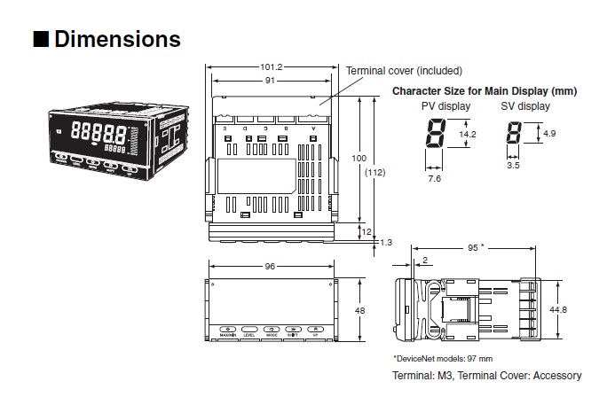
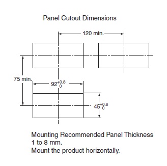
As of July 25, 2024
- Connection diagram
As of July 25, 2024
Terminal arrangement
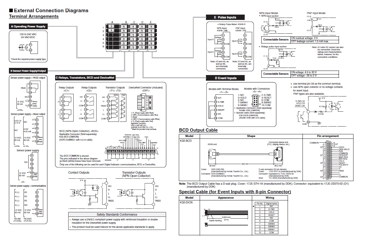
As of July 25, 2024
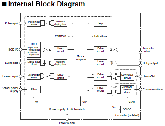
- Internal connection
As of July 25, 2024
As of July 25, 2024
