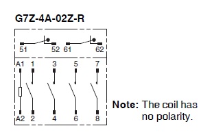
G7Z-4A-02Z-R DC24
Power Relays

Image
Power Relay, 4PST-NO, Auxiliary contact block (DPST-NC), Bifurcated crossbar (Single break), 24 VDC
| Coil ratings |
24 VDC 154 mA |
|---|---|
| Contact form |
Relay: 4PST-NO, Auxiliary contact: DPST-NC |
| Contact method |
Relay: Double break Auxiliary contact block: Single-break |
| Contact material |
Relay: Ag alloy Auxiliary contact block: Au clad + AgNi |
| Contact rated load |
440 VAC 40 A (Relay: Resistive load) 440 VAC 22 A (Relay: Inductive load (cosφ = 0.3)) 440 VAC 1 A (Auxiliary Contact Block: Resistive load) 440 VAC 0.5 A (Auxiliary Contact Block: Inductive load (cosφ = 0.3)) 110 VDC 5 A (Relay: Resistive load (L/R = 1ms)) 110 VDC 0.5 A (Auxiliary Contact Block: Resistive load (L/R = 1ms)) |
| Terminal structure |
Screw terminal |
- Ratings / Performance
As of November 4, 2025
| Degree of protection | Closed type (cover) | |
|---|---|---|
| Terminal structure | Screw terminal | |
| Coil | Coil ratings | 24 VDC 154 mA | Coil resistance | 156 Ω | Operate voltage (Set voltage) | 75 % max. | Release voltage (Reset voltage) | 10 % min. | Maximum voltage | 110 % | Power consumption | Approx. 3.7 W |
| Contact | Contact rated load | 440 VAC 40 A (Relay: Resistive load) 440 VAC 22 A (Relay: Inductive load (cosφ = 0.3)) 440 VAC 1 A (Auxiliary Contact Block: Resistive load) 440 VAC 0.5 A (Auxiliary Contact Block: Inductive load (cosφ = 0.3)) 110 VDC 5 A (Relay: Resistive load (L/R = 1ms)) 110 VDC 0.5 A (Auxiliary Contact Block: Resistive load (L/R = 1ms)) | Max. contact voltage | 480 VAC 125 VDC | Max. contact current | AC: 40 A (Relay: Resistive load) AC: 22 A (Relay: Inductive load (cosφ = 0.3)) AC: 1 A (Auxiliary Contact Block: Resistive load) AC: 0.5 A (Auxiliary Contact Block: Inductive load (cosφ = 0.3)) DC: 5 A (Relay) DC: 0.5 A (Auxiliary contact block) | Maximum switching power | 17600 VA (Relay: Resistive load) 9680 VA (Relay: Inductive load (cosφ = 0.3)) 440 VA (Auxiliary Contact Block: Resistive load) 220 VA (Auxiliary Contact Block: Inductive load (cosφ = 0.3)) 550 W (Relay: Resistive load (L/R = 1ms)) 55 W (Auxiliary Contact Block: Resistive load (L/R = 1ms)) | Contact form | Relay: 4PST-NO, Auxiliary contact: DPST-NC | Contact method | Double break | Contact material | Relay: Ag alloy Auxiliary contact block: Au clad + AgNi |
| Contact resistance | 400 mΩ max. (Voltage drop method with 5 VDC 1 A) 100 mΩ max. (Voltage drop method with 5 VDC 100 mA) |
|---|---|
| Operating time | 50 ms max. (With rated operating power applied, 23 ℃, not including contact bounce) |
| Reset time | 50 ms max. (With rated operating power applied, 23 ℃, not including contact bounce) |
| Maximum operating frequency | Mechanical: 1800 time/hour Rated load: 1200 time/hour |
| Insulation resistance | Between coil and contacts: 1000 MΩ min. (at 1000 VDC) Between contacts of different polarity: 1000 MΩ min. (at 1000 VDC) Between contacts of same polarity: 1000 MΩ min. (at 1000 VDC) |
| Dielectric strength | Between coil and contacts: 4000 VAC 50/60 Hz 1 min Between contacts of different polarity: 4000 VAC 50/60 Hz 1 min Between contacts of same polarity: 2000 VAC 50/60 Hz 1 min |
| Vibration resistance (destruction) | 10 to 55 to 10 Hz, 0.5-mm single amplitude (1-mm double amplitude) |
| Vibration resistance (Malfunction) | NO contact: 10 to 55 to 10 Hz, 0.5-mm single amplitude (1-mm double amplitude) |
| Shock resistance (destruction) | Screw mounting: 700 m/s2, DIN Track mounting: 500 m/s2 |
| Shock resistance (Malfunction) | NO contact: 100 m/s2 |
| Endurance (Mechanical) | 1,000,000 operations min. (under no load at operating frequency of 1800 operations/h) |
| Endurance (Electrical) | AC: 80,000 operations min. (Resistive load/Inductive load, 23 ℃, switching frequency 1,200 operations/h) DC: 100,000 operations min. (Resistive load, 23 ℃, switching frequency 1,200 operations/h) |
| Failure rate | 24 VDC 2 A (failure level: Preference value) |
| Ambient temperature (Operating) | -25 to 60 ℃ (with no freezing or condensation) |
| Ambient humidity (Operating) | 5 to 85 % |
| Mounting method | Screw mounting, DIN track mounting |
As of November 4, 2025
- Dimensions
As of November 4, 2025
Outline drawing
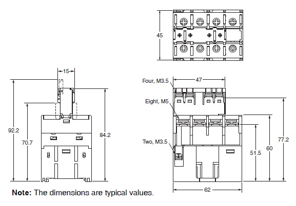
Mounting hole dimensions
As of November 4, 2025
- Terminal arrangement and internal connection
As of November 4, 2025
Terminal arrangement and internal connection
As of November 4, 2025

© Copyright OMRON Corporation 2007 - 2021. All Rights Reserved.