S8VK-WA24024
Switch Mode Power Supply (240/480/960/2000-W Models)
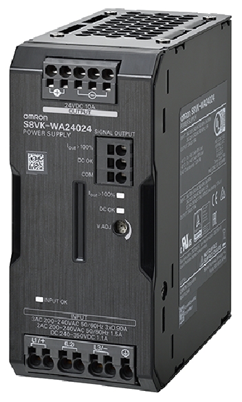
Image
Switch Mode Power Supply, Capacity 240 W, Rated input voltage 200 to 240 VAC, Output voltage 24 V
| Power rating |
240 W |
|---|---|
| Output voltage |
24 V |
| Rated input voltage |
200 to 240 VAC (Three-phase/single-phase/two-phase) |
| Construction |
Covered type |
| Connection |
Terminal blocks |
| Terminal type |
Push-In Plus Terminal Block |
- Specifications
As of July 25, 2024
| Power rating | 240 W | |
|---|---|---|
| Output voltage | 24 V | |
| Efficiency | 93 % typ. (at three-phase 200 VAC input) 92 % typ. (Single-phase/two-phase 200 VAC input Single-phase/two-phase 200 VAC input) 93 % typ. (at three-phase 230 VAC input) 93 % typ. (Single-phase/two-phase 230 VAC input) | |
| Input | Rated input voltage | 200 to 240 VAC (Three-phase/single-phase/two-phase) | Allowable input voltage variable range | 170 to 264 VAC (Three-phase/single-phase/two-phase)/265 to 300 VAC (1 s) 240 to 350 VDC | Frequency | 50/60Hz (47 to 63 Hz) | Rated input current | 0.80 A typ. (at three-phase 200 VAC input) 1.4 A typ. (Single-phase/two-phase 200 VAC input Single-phase/two-phase 200 VAC input) 0.70 A typ. (at three-phase 230 VAC input) 1.2 A typ. (Single-phase/two-phase 230 VAC input) | Power factor | 0.9 min. | Leakage current | 1.0 mA max. (at three-phase 200 VAC input) 1.0 mA max. (at three-phase 230 VAC input) | Inrush current (cold start at 25 ℃) | 13 A typ. (at three-phase 200 VAC input) 15 A typ. (at three-phase 230 VAC input) |
| Output | Rated output current | 10 A | Output voltage variable range | 24 to 29.5 V With V.ADJ | Maximum peak current | 15 A | Ripple | 50 mV(p-p) max. at 20 MHz | Static input variation influence | 0.5 % max. | Static load variation influence | 1.5 % max. | Ambient temperature variation influence | 0.05 %/℃ max. | Start up time | 1000 ms max. (at three-phase 200 VAC input) 1000 ms max. (at three-phase 230 VAC input) | Hold time | 35 ms typ. (at three-phase 200 VAC input) 35 ms typ. (at three-phase 230 VAC input) |
| Additional functions | Overload protection | Yes, automatic reset, intermittent operation type | Overvoltage protection | Yes, 130% or higher of rated output voltage, power shut off (shut off the input voltage and turn on the input again) | Overheat protection | No | Series operation | Yes (Up to 2 Power Supplies with external diode) | Parallel operation | Yes (Up to 2 Power Supplies) | Alarm indication | Yes |
| Insulation | Dielectric strength | Between all input terminals and all output terminals, all signal terminals: 3 kVAC for 1 min, Cut-off current: 20 mA Between all input terminals and PE terminals: 2 kVAC for 1 min, Cut-off current: 20 mA (Between all output terminals, signal output terminals) and PE terminals: 1 kVAC for 1 min, Cut-off current: 25 mA Between all output terminals and all single output terminals: 0.5 kVAC for 1 min, Cut-off current: 10 mA | Insulation resistance | Between all output terminals/all single output terminals and all input terminals/PE terminals: 100 MΩ min., at 500 VDC |
| Environment | Vibration resistance | 10 to 55 Hz, 5 G max., 0.42 mm single amplitude in each 3 directions for 2 hours | Shock resistance | 294 m/s2, 3 times each in 3 axes 6 directions | Altitude | 3000 m max. | Ambient temperature (Operating) | -40 to 70 ℃ | Ambient temperature (Storage) | -40 to 85 ℃ (with no freezing or condensation) | Ambient humidity (Operating) | 95 %RH max. | Ambient humidity (Storage) | 95 %RH max. |
| Reliability | MTBF | 135,000 hours min. | Life expectancy | 10 years min. (at rated input, a load rate of 50% load, under the temperature of 40 ℃ max., standard mounting) |
| Construction | Construction | Covered type | Connection | Terminal blocks | Terminal type | Push-In Plus Terminal Block | Mounting | DIN track mounting | Coationg | Yes | Cooling fan | Cooling fan No | Degree of protection | IP20, EN/IEC 60529 | Weight (Main) | 800 g max. |
Note
Do not use the Inverter output for the Power Supply. Inverters with an output frequency of 50/60 Hz are available, but the rise in the internal temperature of the Power Supply may result in ignition or burning.
As of July 25, 2024
- Dimension
As of July 25, 2024
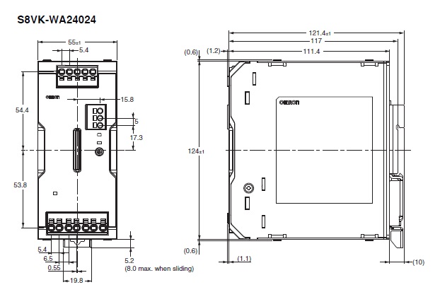
As of July 25, 2024
- Mounting
As of July 25, 2024
Mounting state
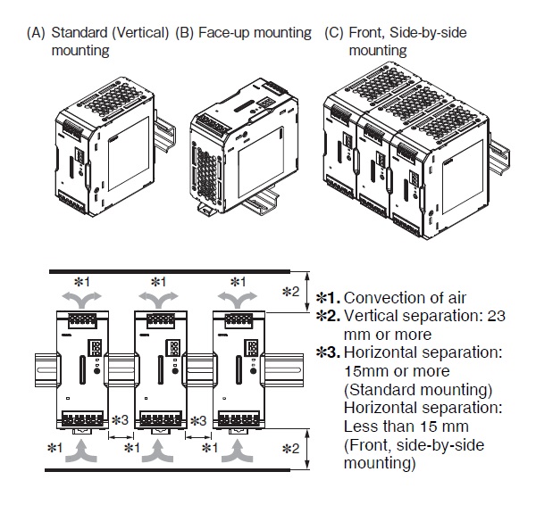
As of July 25, 2024
- Connection diagram
As of July 25, 2024
Terminal arrangement
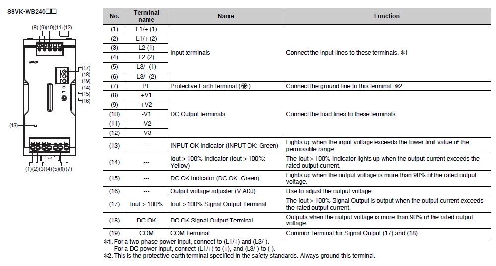
Block diagram
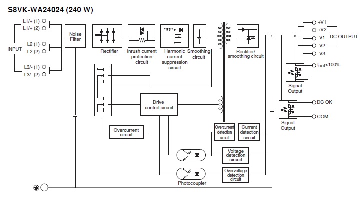
As of July 25, 2024
- Derating curve
As of July 25, 2024
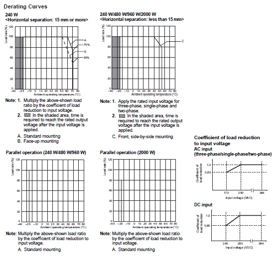
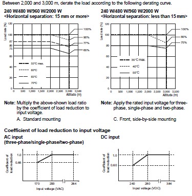
As of July 25, 2024
