Page top

K3HB-H

Temperature Indicator

K3HB-H

New High-speed, High-precision Temperature Indicator

Specifications

Ratings

Power supply voltage 100 to 240 VAC (50/60 Hz), 24 VAC/VDC, DeviceNet power supply: 24 VDC
Allowable power supply voltage
range
85% to 110% of the rated power supply voltage, DeviceNet power supply: 11 to 25
VDC
Power consumption *1 100 to 240 V: 18 VA max. (max. load)
24 VAC/DC: 11 VA/7 W max. (max. load)
Current consumption DeviceNet power supply: 50 mA max. (24 VDC)
Input Platinum-resistance thermometer: Pt100
Thermocouple: K, J, T, E, L, U, N, R, S, B, W
A/D conversion method Delta-Sigma method
External power supply See Sensor Power Supply/Output Type Codes
Event
inputs
*2
Timing input NPN open collector or no-voltage contact signal
ON residual voltage: 3 V max.
ON current at 0Ω: 17 mA max.
Max. applied voltage: 30 VDC max.
OFF leakage current: 1.5 mA max.
Startup compensation
timer input
NPN open collector or no-voltage contact signal
ON residual voltage: 2 V max.
ON current at 0Ω: 4 mA max.
Max. applied voltage: 30 VDC max.
OFF leakage current: 0.1 mA max.
Hold input
Reset input
Bank input
Output
ratings
(depends
on the
model)
Relay output 250 VAC, 30 VDC, 5 A (resistive load)
Mechanical life expectancy: 5,000,000 operations, Electrical life expectancy:
100,000 operations
Transistor output Maximum load voltage: 24 VDC, Maximum load current: 50 mA, Leakage current:
100μ A max.
Linear output Linear output 0 to 20 mA DC, 4 to 20 mA DC:
Load: 500Ω max, Resolution: Approx. 10,000, Output error: ±0.5% FS
Linear output 0 to 5 VDC, 1 to 5 VDC, 0 to 10 VDC:
Load: 5 kΩ max, Resolution: Approx. 10,000, Output error: ±0.5% FS
(1 V or less: ±0.15 V; not output for 0 V or less)
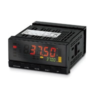
Display method Negative LCD (backlit LED) display
7-segment digital display (Character height: PV: 14.2 mm (green/red); SV: 4.9 mm
(green)
Main functions Temperature input shift, measurement operation selection, averaging, previous
average value comparison, zero-limit, output hysteresis, output OFF delay, output
test, display value selection, display color selection, key protection, bank selection,
display refresh period, maximum/minimum hold, reset
Ambient operating temperature - 10 to 55 °C (with no icing or condensation)
Ambient operating humidity 25% to 85%
Storage temperature -25 to 65 °C (with no icing or condensation)
Altitude 2,000 m max.
Accessories Watertight packing, 2 fixtures, terminal cover, unit stickers, instruction manual.
DeviceNet models also include a DeviceNet connector (Hirose HR31-5.08P-5SC
(01)) and crimp terminals (Hirose HR31-SC-121) *3

*1. DC power supply models require a control power supply capacity of approximately 1 A per Unit when power is turned
      ON. Particular attention is required when using two or more DC power supply models. The OMRON S8VS-series DC
      Power Supply Unit is recommended.
*2. PNP input types are also available.
*3. For K3HB-series DeviceNet models, use only the DeviceNet Connector included with the product. The crimp terminals
      provided are for Thin Cables.

Characteristics

Display range -19,999 to 99,999
Accuracy (at 23±5°C) Thermocouple input: (±0.3% PV or ±1°C, whichever is larger) ± 1 digit max. *
Platinum resistance thermometer input: (±0.2% PV or ±0.8°C, whichever is larger) ± 1 digit max.
Sampling period 20 ms (50 times/second)
Comparative output
response time
Platinum-resistance thermometer input range: 120 ms max.
Thermocouple input range: 180 ms max.
(The time until the comparative output is output when there is a forced sudden change in the input signal from 15% to 95% or 95% to 15%.)
Linear output
response time
Platinum-resistance thermometer input range: 170 ms max.
Thermocouple input range: 230 ms max.
(The time until the final analog output is reached when there is a forced sudden change in the output signal from 15% to 95% or 95% to 15%.)
Insulation resistance 20 MΩ min. (at 500 VDC)
Dielectric strength 2,300 VAC for 1 min between external terminals and case
Noise immunity 100 to 240 VAC models: ±1,500 V at power supply terminals in normal or common mode
(waveform with 1-ns rising edge and pulse width of 1 μs/100 ns)
24 VAC/VDC models: ±1,500 V at power supply terminals in normal or common mode
(waveform with 1-ns rising edge and pulse width of 1 μs/100 ns)
Vibration resistance Frequency: 10 to 55 Hz; Acceleration: 50 m/s2, 10 sweeps of 5 min each in X, Y, and Z directions
Shock resistance 150 m/s2 (100 m/s2 for relay outputs) 3 times each in 3 axes, 6 directions
Weight Approx. 300 g (Base Unit only)
Degree of
protection
Front panel Conforms to NEMA 4X for indoor use (equivalent to IP66)
Rear case IP20
Terminals IP00 + finger protection (VDE0106/100)
Memory protection EEPROM (non-volatile memory)
Number of rewrites: 100,000
Applicable standards UL61010-1, CSA C22.2 No. 61010-1-04
EN61010-1 (IEC61010-1): Pollution degree 2/Overvoltage category II
EN61326-1
EMC EMI: EN61326-1 Industrial electromagnetic environment
Electromagnetic radiation interference: CISPR 11 Group 1, Class A
Terminal interference voltage: CISPR 11 Group 1, Class A
EMS: EN61326-1 Industrial electromagnetic environment
Electrostatic Discharge Immunity: EN61000-4-2: 4 kV (contact), 8 kV (in air)
Radiated Electromagnetic Field Immunity: EN61000-4-3: 10 V/m 1 kHz sine wave amplitude modulation (80 MHz to 1 GHz, 1.4 to 2 GHz)
Electrical Fast Transient/Burst Immunity: EN61000-4-4: 2 kV (power line), 1 kV (I/O signal line)
Surge Immunity: EN61000-4-5: 1 kV with line (power line), 2 kV with ground (power line)
Conducted Disturbance Immunity: EN61000-4-6: 3 V (0.15 to 80 MHz)
Power Frequency Magnetic Immunity: EN61000-4-8: 30 A/m (50 Hz) continuous time
Voltage Dips and Interruptions Immunity: EN61000-4-11: 0.5 cycle, 0°/180°, 100% (rated voltage)

* K, T, N (–100°C or less): ±2°C ±1 digit max.
   U, L: ±2°C ±1 digit max.
   B (400°C max.): Nothing specified.
   R, S (200°C max.): ±3°C ±1 digit max.
   W: (±0.3% PV or ±3°C whichever is larger) ±1 digit max.

Input Ranges

Platinum-resistance Thermometer/Thermocouple

K3HB-H Specifications 7

Celsius/Fahrenheit Correlation Values and Setting/Specified Ranges

K3HB-H Specifications 8

Common Specifications

Event Input Ratings

Input type S-TMR, HOLD, RESET, BANK1, BANK2, BANK4 TIMING
Contact ON: 1 kΩ max., OFF: 100 kΩ min. ---
No-contact ON residual voltage: 2 V max.
OFF leakage current: 0.1 mA max.
Load current: 4 mA max.
Maximum applied voltage: 30 VDC max.
ON residual voltage: 3 V max.
OFF leakage current: 1.5 mA max.
Load current: 17 mA max.
Maximum applied voltage: 30 VDC max.

Output Ratings

Contact Output

Item Resistive loads
(250 VAC, cosφ=1; 30 VDC,
L/R=0 ms)
Inductive loads
(250 VAC, closed circuit,
cosφ=0.4; 30 VDC, L/R=7 ms)
Rated load 5 A at 250 VAC
5 A at 30 VDC
1 A at 250 VAC
1 A at 30 VDC
Mechanical life expectancy 5,000,000 operations
Electrical life expectancy 100,000 operations

Transistor Output

Maximum load voltage 24 VDC
Maximum load current 50 mA
Leakage current 100 μA max.

Linear Output

Item 0 to 20 mA 4 to 20 mA 0 to 5 V 1 to 5 V 0 to 10 V
Allowable load impedance 500 Ω max. 5 kΩ min.
Resolution Approx. 10,000
Output error ±0.5%FS ±0.5%FS (1 V or less: ±0.15 V; not output for 0 V or less)

Serial Communications Output

Item RS-232C, RS-485
Communications method Half duplex
Synchronization method Start-stop synchronization
Baud rate 9,600, 19,200, or 38,400 bps
Transmission code ASCII
Data length 7 bits or 8 bits
Stop bit length 2 bits or 1 bit
Error detection Vertical parity and FCS
Parity check Odd, even

Note: For details on serial and DeviceNet communications, refer to the Digital Indicator K3HB Communications User's
         Manual (Cat.No. N129).

BCD Output I/O Ratings (Input Signal Logic: Negative)

I/O signal name Item Rating
Inputs REQUEST
HOLD
MAX
MIN
RESET
Input signal No-voltage contact input
Input current for no-voltage input 10 mA
Signal level ON voltage 1.5 V max.
OFF voltage 3 V min.
Outputs DATA
POLARITY
OVER
DATA VALID
RUN
Maximum load voltage 24 VDC
Maximum load current 10 mA
Leakage current 100 μA max.
HH
H
PASS
L
LL
Maximum load voltage 24 VDC
Maximum load current 50 mA
Leakage current 100 μA max.

Note: For details on serial and DeviceNet communications, refer to the Digital Indicator K3HB Communications User's
         Manual (Cat.No. N129).

DeviceNet Communications

Communications protocol Conforms to DeviceNet
Supported
communi-
cations
Remote I/O
communications
Master-Slave connection (polling, bit-strobe, COS, cyclic)
Conforms to DeviceNet communications standards.
I/O allocations Allocate any I/O data using the Configurator.
Allocate any data, such as DeviceNet-specific parameters and variable area for Digital
Indicators.
Input area: 2 blocks, 60 words max.
Output area: 1 block, 29 words max.
(The first word in the area is always allocated for the Output Execution Enabled Flags.)
Message
communications
Explicit message communications
CompoWay/F communications commands can be executed (using explicit message
communications)
Connection methods Combination of multi-drop and T-branch connections (for trunk and drop lines)
Baud rate DeviceNet: 500, 250, or 125 Kbps (automatic follow-up)
Communications media Special 5-wire cable (2 signal lines, 2 power supply lines, 1 shield line)
Communications distance Baud rate Network length
(max.)
Drop line length
(max.)
Total drop line
length (max.)
500 Kbps 100 m (100 m) 6 m 39 m
250 Kbps 100 m (250 m) 6 m 78 m
125 Kbps 100 m (500 m) 6 m 156 m
The values in parentheses are for Thick Cable.
Communications power supply 24-VDC DeviceNet power supply
Allowable voltage fluctuation
range
11 to 25-VDC DeviceNet power supply
Current consumption 50 mA max. (24 VDC)
Maximum number of nodes 64 (DeviceNet Configurator is counted as one node when connected)
Maximum number of slaves 63
Error control checks CRC errors
DeviceNet power supply Supplied from DeviceNet communications connector