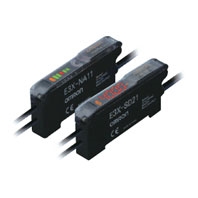
Page top

E3X-SD / NA

Simple Fiber Amplifier Unit

E3X-SD / NA

Simple and Affordable Fiber Amplifier Units

Fiber Amplifier Units

Type Digital display and direct key
setting
Bar display and adjuster setting
Standard models Standard
models
High-speed
detection
models
Water-resistant
models
Model E3X-SD[] E3X-NA[] E3X-NA[]F E3X-NA[]V
Light source
(wavelength)
Red, 4-element LED (625 nm) Red,
4-element
LED (624 nm)
Red,
4-element
LED (625 nm)
Red LED (680 nm)
Power supply voltage 12 to 24 VDC ±10%, ripple (p-p): 10% max.
Power consumption/
Current consumption
At Power Supply Voltage of 24 VDC
960 mW max./40 mA max.
At Power Supply Voltage of 12 VDC
960 mW max./80 mA max.
At Power Supply Voltage of 24 VDC
840 mW max./35 mA max.
At Power Supply Voltage of 12 VDC
420 mW max./35 mA max.
Control output Open-collector output (NPN or PNP)
Load power supply: 26.4 V max.,
Load current: 50 mA max.
(Residual voltage: 1.5 V max.)
Light-ON/Dark-ON mode selector
Open-collector output (NPN or PNP)
Load power supply: 26.4 V max.,
Load current: 50 mA max.
(Residual voltage: 1 V max.)
Light-ON/Dark-ON mode selector.
Response time Operate or reset: 200 μs max. *1 Operate:
20 μs max.
Reset:
30 μs max.
Operate or reset:
200 μs max. *1
Sensitivity adjustment UP/DOWN direct key setting,
teaching with/without a workpiece,
automatic teaching
8-turn sensitivity adjuster (with indicator)
Protection circuits Power supply reverse polarity
protection,
output short-circuit protection,
output reverse polarity protection
Power supply reverse polarity protection,
output short-circuit protection
Timer function --- No timer, OFF-delay timer; or Timer selector
(timer time: 40 ms (fixed))
Mutual interference
prevention
Up to 5 Amplifiers (optically synchronized) *2 None Up to 5 Amplifiers
(optically
synchronized) *2
Ambient illumination Receiver side
Incandescent lamp: 10,000 lux max.
Sunlight: 20,000 lux max.
Number of gang-
mounted Amplifiers
16 max. (The ambient temperature specification depends on the number of gang-mounted
Amplifiers.)
Ambient temperature
range
Operating: Groups of 1 to 3 Amplifiers: - 25 °C to 55 °C
Groups of 4 to 11 Amplifiers: - 25 °C to 50 °C
Groups of 12 to 16 Amplifiers: - 25 °C to 45 °C
Storage: - 30 °C to 70 °C (with no icing or condensation)
Ambient humidity range Operating and storage: 35% to 85%
(with no condensation)
Operating: 35% to 85%
Storage: 35% to 95%
(with no condensation)
Insulation resistance 20 MΩ. min. (at 500 VDC)
Dielectric strength 1,000 VAC at 50/60 Hz for 1 minute *3
Vibration resistance Destruction: 10 to 55 Hz with a 1.5-mm double amplitude for 2 hours each in X, Y and Z
directions
Shock resistance Destruction: 500 m/s2, for 3 times each in X, Y and Z directions
Degree of protection IEC 60529 IP50 (with Protective Cover attached) IEC 60529 IP66
(with Protective
Cover attached)
Connection method Pre-wired (standard cable length: 2 m), or connector
Weight (packed state) *4 Pre-wired model: Approx. 100 g, Model with connector: Approx. 55 g
Material Case Polybutylene terephthalate (PBT)
Cover Polycarbonate (PC) Polyethersulfone
(PES)
Accessories Instruction manual

*1. When there are 8 or more E3X-NA Amplifiers mounted side-by-side, the response time will be 350 μs max.
*2. Mutual interference prevention is effective when E3X-SD/-NA-series Fiber Amplifier Units are gang-mounted without other E3X-series Fiber Amplifier Units.
*3. Water-resistant models and models with connectors have a dielectric strength of 500 VAC.
*4. Add 10 g for water-resistant models.

Amplifier Unit Connectors (Wire-saving Connectors)

Model E3X-CN11 E3X-CN12
Rated current 2.5 A
Rated voltage 50 V
Contact resistance 20 mΩ max. (20 mVDC max., 100 mA max.)
(The above figure is for connection to the Fiber Amplifier Unit and the adjacent Connector. It
does not include the conductor resistance of the cable.)
Number of insertions Destruction: 50 times (for connection to the Fiber Amplifier Unit and the adjacent Connector)
Material Housing Polybutylene terephthalate (PBT)
Contact Phosphor bronze/gold-plated nickel
Weight (packed state) Approx. 55 g Approx. 25 g

Sensing distance

Threaded Models

Detection method Sensing direction Size Model Sensing distance (mm)
E3X-SD[]
E3X-NA[]
E3X-NA[]F E3X-NA[]V
Through-beam Right-angle M4 E32-T11N 2M 530 160 280
E32-LT11N 2M 1,800 600 900
Straight E32-T11R 2M 560 160 280
E32-LT11 2M 2,100 700 1,050
E32-LT11R 2M 1,800 600 900
Reflective Right-angle M3 E32-C31N 2M 25 7.5 13
E32-C21N 2M 65 21 32
M4 E32-D21N 2M 170 56 85
M6 E32-C11N 2M 170 50 85
E32-LD11N 2M 170 56 85
Straight M3 E32-D21R 2M 30 10 15
E32-C31 2M 80 26 40
E32-C31M 1M
M4 E32-D211R 2M 30 10 15
M6 E32-D11R 2M 180 60 90
E32-CC200 2M 300 100 150
E32-LD11 2M 180 60 90
E32-LD11R 2M 170 56 85

Cylindrical Models

Detection method Size Sensing direction Model Sensing distance (mm)
E3X-SD[]
E3X-NA[]
E3X-NA[]F E3X-NA[]V
Through-beam 1 dia. Top-view E32-T223R 2M 120 36 60
1.5 dia. E32-T22B 2M 200 60 100
3 dia. E32-T12R 2M 560 160 280
Side-view E32-T14LR 2M 220 66 110
Reflective 1.5 dia. Top-view E32-D22B 2M 30 10 15
1.5 dia. + 0.5 dia. E32-D43M 1M 6 2 3
3 dia. E32-D22R 2M 30 10 15
E32-D221B 2M 70 20 35
E32-D32L 2M 160 50 80
3 dia. + 0.8 dia. E32-D33 2M 16 4 10

Flat Models

Detection method Sensing direction Model Sensing distance (mm)
E3X-SD[]
E3X-NA[]
E3X-NA[]F E3X-NA[]V
Through-beam Top-view E32-T15XR 2M 560 160 280
Side-view E32-T15YR 2M 220 66 110
Flat-view E32-T15ZR 2M
Reflective Top-view E32-D15XR 2M 180 60 90
Side-view E32-D15YR 2M 40 10 20
Flat-view E32-D15ZR 2M

Sleeve Models

Detection method Sensing direction Model Sensing distance (mm)
E3X-SD[]
E3X-NA[]
E3X-NA[]F E3X-NA[]V
Through-beam Side-view E32-T24R 2M 60 18 30
E32-T24E 2M 180 36 60
Top-view E32-T21-S1 2M 130 43 65
E32-T33 1M 40 13.5 20
E32-TC200BR 2M 560 160 280
Reflective Side-view E32-D24R 2M 14 4.6 7
E32-D24-S2 2M 26 8 13
Top-view E32-D43M 1M 6 2 3
E32-D331 2M 3 1 1.5
E32-D33 2M 16 4 10
E32-D32-S1 0.5M 14 4 7
E32-D31-S1 0.5M
E32-DC200F4R 2M 30 10 15
E32-D22-S1 2M 57 19 28
E32-D21-S3 2M
E32-DC200BR 2M 180 60 90
E32-D25-S3 2M 57 19 28

Small-spot, Reflective

Type Spot
diameter
Center distance
(mm)
Model Sensing distance (mm)
E3X-SD[]
E3X-NA[]
E3X-NA[]F E3X-NA[]V
Variable
spot
0.1 to
0.6 dia.
6 to 15 E32-C42 1M + E39-F3A Spot diameter of 0.1 to 0.6 mm at 6 to 15 mm.
0.3 to
1.6 dia.
10 to 30 E32-C42 1M + E39-F17 Spot diameter of 0.3 to 1.6 mm at 10 to 30 mm.
Parallel
light
4 dia. 0 to 20 E32-C31 2M + E39-F3C Spot diameter of 4 mm max. at 0 to 20 mm.
E32-C31N 2M + E39-F3C
Integrated
lens
0.1 dia. 5 E32-C42S 1M Spot diameter of 0.1 mm at 5 mm.
6 dia. 50 E32-L15 2M Spot diameter of 6 mm at 50 mm.
Small-
spot
0.1 dia. 7 E32-C41 1M + E39-F3A-5 Spot diameter of 0.1 mm at 7 mm.
0.5 dia. E32-C31 2M + E39-F3A-5 Spot diameter of 0.5 mm at 5 mm.
E32-C31N 2M + E39-F3A-5
0.2 dia. 17 E32-C41 1M + E39-F3B Spot diameter of 0.2 mm at 17 mm.
0.5 dia. E32-C31 2M + E39-F3B Spot diameter of 0.5 mm at 17 mm.
E32-C31N 2M + E39-F3B
3 dia. 50 E32-CC200 2M + E39-F18 Spot diameter of 3 mm at 50 mm.
E32-C11N 2M + E39-F18

High-power Beam

Type Sensing
direction
Aperture
angle
Model Sensing distance (mm)
E3X-SD[]
E3X-NA[]
E3X-NA[]F E3X-NA[]V
Through-beam
Integrated lens
Right-angle 15° E32-LT11N 2M 1,800 600 900
Top-view 10° E32-T17L 10M 20,000 *1 8,400 14,000
15° E32-LT11 2M 2,100 700 1,050
15° E32-LT11R 2M 1,800 600 900
Side-view 30° E32-T14 2M 3,600 1,080 1,800
Through-beam
models with
lenses
Right-angle 12° E32-T11N 2M + E39-F1 3,700 1,110 2,100
E32-T11N 2M + E39-F16 4,000 *2 2,000 3,600
Top-view 12° E32-T11R 2M + E39-F1 4,000 *2 1,260 2,100
E32-T11R 2M + E39-F16 4,000 *2 2,000 3,600
Side-view 60° E32-T11R 2M + E39-F2 440 130 220
Top-view 12° E32-T11 2M + E39-F1 4,000 *2 1,200 2,000
E32-T11 2M + E39-F16 4,000 *2 2,600 4,000 *2
Side-view 60° E32-T11 2M + E39-F2 720 200 360
Top-view 12° E32-T51R 2M + E39-F1 2,000 720 1,650
E32-T51R 2M + E39-F16 4,000 *2 1,560 2,900
Side-view 60° E32-T51R 2M + E39-F2 360 120 200
Top-view 12° E32-T81R-S 2M + E39-F1 1,800 630 1,100
E32-T81R-S 2M + E39-F16 4,000 *2 1,300 2,300
Side-view 60° E32-T81R-S 2M + E39-F2 280 84 140
Top-view 12° E32-T61-S 2M + E39-F1 4,000 *2 1,800 3,000
E32-T61-S 2M + E39-F16 4,000 *2 2,340 3,900
Side-view 60° E32-T61-S 2M + E39-F2 780 260 390
Top-view 12° E32-T51 2M + E39-F1-33 2,400 720 1,400
E32-T51 2M + E39-F16 4,000 *2 3,120 4,000 *2
Reflective
Integrated lens
Top-view E32-D16 2M 800 140 40 to 400

*1. The fiber length is 10 m on each side, so the sensing distance is given as 20,000 mm.
*2. The fiber length is 2 m on each side, so the sensing distance is given as 4,000 mm.

Narrow View

Detection method Sensing
direction
Aperture angle Model Sensing distance (mm)
E3X-SD[]
E3X-NA[]
E3X-NA[]F E3X-NA[]V
Through-beam Side-view 1.5° E32-A03 2M 890 267 445
E32-A03-1 2M
3.4° E32-A04 2M 340 102 170
E32-T24SR 2M 1170 360 600
E32-T24S 2M 1400 420 700
E32-T22S 2M 2000 600 1000

Detection without Background Interference

Detection
method
Sensing
direction
Model Sensing distance (mm)
E3X-SD[]
E3X-NA[]
E3X-NA[]F E3X-NA[]V
Limited-
reflective
Flat-view E32-L16-N 2M 0 to 15 0 to 12 0 to 15
E32-L24S 2M 0 to 4
Side-view E32-L25L 2M 5.4 to 9 (center 7.2) 5.4 to 8 (center 7.2) 5.4 to 9 (center 7.2)

Transparent Object Detection (Retro-reflective)

Detection
method
Feature Size Model Sensing distance (mm)
E3X-SD[]
E3X-NA[]
E3X-NA[]F E3X-NA[]V
Retroreflective
Sensors
Film detection M3 E32-C31 2M +
E39-F3R + E39-RP37
220 50 75
Square - E32-R16 2M 1,500 1,000 150 to 1,500
Threaded Models M6 E32-R21 2M 10 to 250 250 10 to 250
Hex-shaped E32-LR11NP 2M +
E39-RP1
600 200 300

Transparent Object Detection (Limited-reflective)

Detection
method
Feature Sensing
direction
Model Sensing distance (mm)
E3X-SD[]
E3X-NA[]
E3X-NA[]F E3X-NA[]V
Retro-
reflective
Small size Flat-view E32- L24S 2M 0 to 4
Standard E32-L16-N 2M 0 to 15 0 to 12 0 to 15
Glass substrate
alignment, 70°C
E32-A08 2M 10 to 20
Standard/
long-distance
E32-A12 2M 12 to 30 - -
Side view form Side-view E32-L25L 2M 5.4 to 9
(center 7.2)
5.4 to 8
(center 7.2)
5.4 to 9
(center 7.2)
Glass substrate
mapping, 70°C
Top-view E32-A09 2M 15 to 38 (center 25)

Chemical-resistant, Oil-resistant

Detection
method
Type Sensing
direction
Model Sensing distance (mm)
E3X-SD[]
E3X-NA[]
E3X-NA[]F E3X-NA[]V
Through-
beam
Oil-resistant Right-angle E32-T11NF 2M 4,000 * 1,400 2,400
Chemical/
oil-resistant
Top-view E32-T12F 2M 3,200 960 1,600
E32-T11F 2M 2,100 760 1,050
Side-view E32-T14F 2M 400 120 200
Chemical/oil-
resistant at 150°C
Top-view E32-T51F 2M 1,400 400 700
Reflective Semiconductors:
Cleaning, developing,
and etching; 60°C
Top-view E32-L11FP 2M 8 to 20 mm from tip of lens (Recommended sensing
distance: 11 mm), 19 to 31 mm from center of
mounting hole A (Recommended sensing distance:
22 mm)
Semiconductors:
Resist stripping;
85°C
E32-L11FS 2M 8 to 20 mm from tip of lens (Recommended sensing
distance: 11 mm), 32 to 44 mm from center of
mounting hole A (Recommended sensing distance:
35 mm)
Chemical/
oil-resistant
E32-D12F 2M 100 32 50
Chemical-resistant
cable
E32-D11U 2M 180 60 90
*The fiber length is 2 m on each side, so the sensing distance is given as 4,000 mm.

Bending-resistant

Detection method Size Model Sensing distance (mm)
E3X-SD[]
E3X-NA[]
E3X-NA[]F E3X-NA[]V
Through-beam 1.5 dia. E32-T22B 2M 200 60 100
M3 E32-T21 2M
M4 E32-T11 2M 720 200 360
Square E32-T25XB 2M 150 40 75
Reflective 1.5 dia. E32-D22B 2M 30 10 15
M3 E32-D21 2M
3 dia. E32-D221B 2M 70 20 35
M4 E32-D21B 2M
M6 E32-D11 2M 180 60 90
Square E32-D25XB 2M 50 16 25

Heat-resistant

Detection method Heat-resistant temperature Model Sensing distance (mm)
E3X-SD[]
E3X-NA[]
E3X-NA[]F E3X-NA[]V
Through-beam 100°C E32-T51R 2M 400 120 225
150°C E32-T51 2M 800 240 400
200°C E32-T81R-S 2M 360 100 180
350°C E32-T61-S 2M 600 180 300
Reflective 100°C E32-D51R 2M 140 42 70
150°C E32-D51 2M 240 80 120
200°C E32-D81R 2M 90 27 45
300°C E32-A08H2 2M 10 to 20
E32-A09H2 2M 20 to 30 (center 25)
350°C E32-D61 2M 90 27 45
400°C E32-D73 2M 60 18 30

Area Beam

Detection method Type Sensing width Model Sensing distance (mm)
E3X-SD[]
E3X-NA[]
E3X-NA[]F E3X-NA[]V
Through-beam Area 11 mm E32-T16PR 2M 800 260 450
E32-T16JR 2M 700 220 390
30 mm E32-T16WR 2M 1380 400 690
Reflective Array 11 mm E32-D36P1 2M 150 50 75

Liquid-level Detection

Detection
method
Pipe
diameter
Feature Model Sensing distance (mm)
E3X-SD[]
E3X-NA[]
E3X-NA[]F E3X-NA[]V
Tube-mounting 3.2/6.4/
9.5 dia.
Stable residual
quantity detection
E32-A01 5M Applicable tube: Transparent tube with a diameter
of 3.2, 6.4, or 9.5 mm, Recommended wall
thickness: 1 mm
8 to 10 dia. Mounting at multi
levels
E32-L25T 2M Applicable tube: Transparent tube with a diameter
of 8 to 10 mm, Recommended wall thickness:
1 mm
No re-
strictions
Large tubes E32-D36T 2M Applicable tube: Transparent tube (no restrictions
on diameter)
Liquid contact
(heat-resistant
up to 200°C)
- - E32-D82F1 4M Liquid-contact model

Vacuum-resistant

Detection method Heat-resistant
temperature
Model Sensing distance (mm)
E3X-SD[]
E3X-NA[]
E3X-NA[]F E3X-NA[]V
Through-beam 120°C E32-T51V 1M 200 - 100
E32-T51V 1M + E39-F1V 1200 - 600
200°C E32-T84SV 1M 500 - 250

FPD, Semiconductors, and Solar Cells

Detection
method
Application Operating
temperature
Model Sensing distance (mm)
E3X-SD[]
E3X-NA[]
E3X-NA[]F E3X-NA[]V
Limited-
reflective
Glass presence
detection
70°C E32-L16-N 2M 0 to 15 0 to 12 0 to 15
Glass substrate
alignment
E32-A08 2M 10 to 20
300°C E32-A08H2 2M
70°C E32-A12 2M 12 to 30 - -
Glass substrate
mapping
E32-A09 2M 15 to 38 (center 25)
300°C E32-A09H2 2M 20 to 30 (center 25)
Wet processes:
Cleaning, Resist
developing and
etching
60°C E32-L11FP 2M 8 to 20 mm from tip of lens (Recommended sensing
distance: 11 mm), 19 to 31 mm from center of
mounting hole A (Recommended sensing distance:
22 mm)
Wet process:
Resist stripping
85°C E32-L11FS 2M 8 to 20 mm from tip of lens (Recommended sensing
distance: 11 mm), 32 to 44 mm from center of
mounting hole A (Recommended sensing distance:
35 mm)
Through-
beam
Wafer mapping 70°C E32-A03 2M 890 267 445
E32-A03-1 2M
E32-A04 2M 340 102 170
E32-T24SR 2M 1170 360 600
E32-T24S 2M 1400 420 700