| Model | G9SX-NS202-[] | G9SX-NSA222-T03-[] | G9SX-EX-[] |
|---|---|---|---|
| Rated supply voltage | 24 V DC | ||
| Operating voltage range | -15% to 10% of rated supply voltage | ||
| Rated power consumption * | 3 W max. | 4 W max. | 2 W max. |
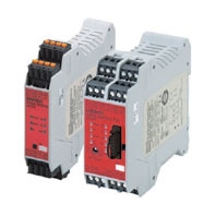
Non-Contact Door Switch Controller
Related Contents
last update: May 16, 2022
| Model | G9SX-NS202-[] | G9SX-NSA222-T03-[] | G9SX-EX-[] |
|---|---|---|---|
| Rated supply voltage | 24 V DC | ||
| Operating voltage range | -15% to 10% of rated supply voltage | ||
| Rated power consumption * | 3 W max. | 4 W max. | 2 W max. |
* Power consumption of loads not included.
| Model | G9SX-NS202-[]/G9SX-NSA222-T03-[] |
|---|---|
| Safety input *1 | Operating voltage: 20.4 VDC to 26.4 VDC, internal impedance: approx. 2.8 kΩ *2 |
| Feedback/reset input |
*1. Only applies to the G9SX-NSA222-T03-[]. Refers to input other than that from the Non-contact Door Switch.
*2. Provide a current equal to or higher than that of the minimum applicable load of the connected input control device.
| Model | G9SX-NS202-[]/G9SX-NSA222-T03-[] |
|---|---|
| Instantaneous safety output *1
OFF-delayed safety output *1 |
P channel MOS FET transistor output
Load current: 0.8 A DC max. *2 |
| Auxiliary output | PNP transistor output
Load current: 100 mA max. |

| Model | G9SX-EX-[] |
|---|---|
| Rated load | 250 VAC, 3 A/30 VDC, 3 A (resistive load) |
| Rated carry current | 3 A |
| Maximum switching voltage | 250 VAC, 125 VDC |
| Model | G9SX-NS202-[] | G9SX-NSA222-T03-[] | G9SX-EX-[] | |
|---|---|---|---|---|
| Over-voltage category
(IEC/EN 60664-1) |
II | II (Relay outputs 13 to
43 and 14 to 44: III) |
||
| Operating time (OFF to ON state) *1 | Logical AND connection
input: 100 ms max. D40A connected: 100 ms max. D40Z connected: 200 ms max. |
Safety input: 50 ms max. *2
Logical AND connection input: 100 ms max. *3 D40A connected: 100 ms max. *3 D40Z connected: 200 ms max. *3 |
30 ms max. *4 | |
| Response time (ON to OFF state) *1 | 15 ms max. (Logical
AND connection input: OFF) Logical AND connection input: 15 ms max. D40A connected: 20 ms max. *6 D40Z connected: 45 ms max. |
15 ms max. (Logical AND
connection input: OFF) Safety input: 15 ms max. Logical AND connection input: 15 ms max. D40A connected: 20 ms max. *6 D40Z connected: 45 ms max. |
10 ms max. *4 | |
| ON-state residual voltage | 3.0 V max. (safety output, auxiliary output) | |||
| OFF-state leakage current | 0.1 mA max. (safety output, auxiliary output) | |||
| Maximum wiring length of safety
input, logical AND connection input, and Non-contact Door Switch input |
100 m max. (External connection impedance: 100 Ω max. and 10 nF max.) | |||
| Reset input time
(Reset button pressing time) |
100 ms min. | |||
| Accuracy of OFF-delay time *5 | --- | Within ±5% of the set
value |
Within ±5% of the set
value |
|
| Insulation
resistance |
Between logical AND
connection terminals, and power supply input terminals and other input and output terminals connected together |
20 MΩ min. (at 100 VDC) | --- | |
| Between all terminals
connected together and DIN rail |
100 MΩ min.
(at 500 VDC) |
|||
| Dielectric
strength |
Between logical AND
connection terminals, and power supply input terminals and other input and output terminals connected together |
500 VAC for 1 min. | --- | |
| Between all terminals
connected together and DIN rail |
1,200 VAC for 1 min | |||
| Between different poles
of outputs |
--- | |||
| Between relay outputs
connected together and other terminals connected together |
2,200 VAC for 1 min | |||
| Vibration resistance | 10 to 55 to 10 Hz, 0.375 mm single amplitude (0.75 mm double amplitude) | |||
| Shock
resistance |
Destruction | 300 m/s2 | ||
| Malfunction | 100 m/s2 | |||
| Durability | Electrical | --- | 100,000 cycles min.
rated load, switching frequency: 1,800 cycles/hour) |
|
| Mechanical | --- | 5,000,000 cycles min.
(switching frequency: 7,200 cycles/hour) |
||
| Ambient operating temperature | -10 to 55°C (no icing or condensation) | |||
| Ambient operating humidity | 25% to 85% | |||
| Terminal tightening torque | 0.5 N·m (For the G9SX-NS[]-RT (with screw terminals) only) | |||
| Weight | Approx. 125 g | Approx. 200 g | Approx. 165 g | |
last update: May 16, 2022
© Copyright OMRON Corporation 2007 - 2024. All Rights Reserved.