Cam Positioners
Cam Positioners detect angles of rotation by means of absolute encoders and give output signals according to the preset ON and OFF angles (Cam program).
| Introduction |
|
|
|
Classifications |
| Engineering Data |
|
|
|
Troubleshooting |
-
 What is a Cam Positioner?
-
 Resolver
-
 What Is a Cam Positioner?
-
 What Is a Resolver?
-
 What Is an Absolute Encoder?
-
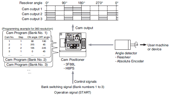
 Description of Operation
-
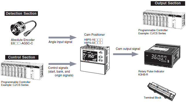
 Configuration Example
-
 Features
-
 Operating Principle
What Is a Cam Positioner?
Traditionally, a mechanical cam and limit switch (or a photoelectric sensor or other sensor) were used to detect rotational angles.
A Cam Positioner electrically achieves the function of traditional mechanical cams.
A Cam Positioner reads the angle data from an input detection device (a Resolver or Encoder) and turns an output ON and OFF according to preset ON/OFF angles (called the cam program).
In food packing machines, for example, the Cam Positioner uses angle position data to control the timing of various mechanisms.
The purpose of Cam Positioners is generally this type of timing control.


What Is a Resolver?
A Resolver is a type of sensor that detects angles.
Unlike Encoders, Resolvers have a simple structure and have no electronic parts. Their performance is therefore less affected by dust and vibration in comparison with Encoders. This makes them highly reliable and environmentally resistant. Because they are brushless as well, they are maintenance free and their service life depends solely on the ball bearings.

What Is an Absolute Encoder?
An Absolute Encoder is a type of sensor that detects angles. It is a Rotary Encoder that outputs the rotational angle with an absolute code.
The code is read optically or electromagnetically to detect the rotational position.

Description of Operation
This section describes the basic operation of a Cam Positioner.
First, a cam program (the ON/OFF pattern for the cam output) is input into the Cam Positioner. Turning the cam output ON and OFF is set up by setting the ON and OFF angles.
The cam program can be selected by setting a bank number with bank switching signals. The Cam Positioner starts operation when the operation signal is turned ON.

Configuration Example
Using a Resolver to Detect Angles

Features
Environmental Resistance
Resolvers have no electronic parts, and therefore have superior environmental resistance in comparison with Encoders, against oil, dust, temperature, and shock.
They also have an ambient operating temperature range of -10 to 80°C..
Absolute Angle Detection
Resolvers can detect absolute angles and only one Resolver is needed for high precision at a 360 or 720 resolution.
Shaft-load Tolerance: 196 N, Shaft Diameter: 10 mm
(3F88L-RS17/RS17T)
With radial and thrust shaft-load tolerances of 196 N, Resolvers generally outperform other detectors, such as Encoders.
Maximum Cable Length Up to 100 m
Resolver cables can be extended up to 100 m to enable remote operation and control from a location well away from the Resolver.
Operating Principle
As shown in the following diagram, sin θ and cos θ voltage is applied to the two sets of fixed windings, S1 - S3 and S2 - S4, respectively,
that are mechanically 90° out of phase. Observing the sin (θ - α) voltage induced in the rotating winding R1 - R2 makes the Resolver a kind of rotating transformer that detects angles.

If the fixed winding is locked in position completely in phase with fixed winding S1 - S3 (energized by sin θ voltage) for example, then sin θ voltage will be induced in R1 - R2. When
the rotating winding starts rotating, sin (θ - α) voltage will be induced in R1 - R2 because of the cos θ voltage of the S2 - S4 winding that is 90° out of phase with the S1 - S3 winding.
(See the figure below.)
A phase (time) delay or advance of α is detected and measured to determine the absolute angle.

Using an Absolute Encoder to Detect Angles

Refer to the Technical Explanation for Rotary Encoders for information on the features and operating principles of Absolute Encoders.