D4CC-1024
Miniature Limit Switch
Image
Small Limit Switch, Roller lever, 1 A at 125 VAC
| Shape/Structure |
General-purpose Limit switches |
|---|---|
| Actuator |
Roller lever |
| Electrical ratings |
1 A at 125 VAC |
| Contact form |
SPDT |
| Degree of protection |
IP67 |
- Ratings / Performance
As of August 8, 2024
| Shape/Structure | General-purpose Limit switches |
|---|---|
| ctuator | Roller lever 17.5 dia. x 7 Sintered stainless steel roller |
| Electrical ratings | 1 A at 125 VAC |
| Frequency | 50/60 Hz |
| Contact form | SPDT |
| Load | General load |
| Ratings (AC): Non-Inductive load | Resistive load: 1 A at 125 VAC Lamp load (NC): 1 A at 125 VAC Lamp load (NO): 7 A at 125 VAC Inductive load: 1 A at 125 VAC Motor load: 1 A at 125 VAC |
| Inrush current | NC: 5 A max. NO: 2.5 A max. |
| Ambient temperature | Operating: -10 to 70 ℃ (with no icing) |
| Ambient humidity | 35 to 95 % |
| Permissible operating speed | 1 mm/s to 1 m/s |
|---|---|
| Permissible operating frequency | Electrical: 30 operations / 1 minute max. Mechanical: 120 operations / 1 minute max. |
| Contact resistance (Initial value) | 100 mΩ max. |
| Insulation resistance | 100 MΩ min. (at 500 VDC) |
| Dielectric strength | Between each terminal of the same polarities: 1,000 VAC 50/60 Hz 1 min Between live-metallic part and ground: 1,500 VAC 50/60 Hz 1 min Between each terminal and non-live-metallic part: 1,500 VAC 50/60 Hz 1 min |
| Durability | Electrical: 200,000 operations min. (1 A at 125 VAC) Mechanical: 10 million operations min. |
| Vibration resistance | Malfunction: 10 to 55 Hz, 1.5 mm double amplitude |
| Shock resistance | Destruction: 1,000 m/s2 max. Malfunction: 500 m/s2 max. |
| Degree of protection | IP67 |
| Operating Force (OF) | Standard value 5.69 N max. |
|---|---|
| Release Force (RF) | Standard value 1.47 N min. |
| Pre-Travel (PT) | Standard value 10±3 ° |
| Movement Differential (MD) | Standard value 3 ° max. |
| Over-Travel (OT) | Standard value 50 ° min. |
As of August 8, 2024
- Dimensions
As of August 8, 2024
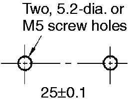
Mounting hole dimensions
As of August 8, 2024
- Circuits configuration
As of August 8, 2024
Connector pin arrangement
As of August 8, 2024

© Copyright OMRON Corporation 2007 - 2021. All Rights Reserved.