D4ER-2C21N-DTK1EJ
Oil-resistant Limit Switch

Image
Oil-resistant Limit Switch, Plunger, 0.1 A at 30 VDC, Right-hand cable, Pre-wired connector
| Shape/Structure |
Enclosed Limit switches |
|---|---|
| Actuator |
Plunger |
| Electrical ratings |
0.1 A at 30 VDC |
| Contact form |
SPDT |
| Cable specifications |
Oil-resistant cable, 0.3 m |
- Ratings / Performance
As of August 8, 2024
| Shape/Structure | Enclosed Limit switches |
|---|---|
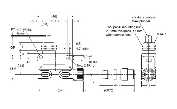
| ctuator | Plunger 7.8 dia. Stainless steel plunger |
| Electrical ratings | 0.1 A at 30 VDC |
| Contact form | SPDT |
| Load | Micro load |
| Ratings (DC): Non-Inductive load | Resistive load: 0.1 A at 8 VDC/0.1 A at 14 VDC/0.1 A at 30 VDC |
| Cable specifications | Oil-resistant cable, 0.3 m Location of lead output: Right-hand |
| Ambient temperature | Operating: 5 to 70 ℃ (with no freezing or condensation) Storage: 5 to 70 ℃ (with no freezing or condensation) |
| Ambient humidity | 35 to 95 % (with no condensation) |
| Permissible operating speed | 0.1 mm/s to 0.5 m/s |
|---|---|
| Permissible operating frequency | Electrical: 30 operations / 1 minute max. Mechanical: 120 operations / 1 minute max. |
| Contact resistance (Initial value) | 50 mΩ max. (initial value for the built-in switch whentested alone) |
| Insulation resistance | 100 MΩ min. (at 500 VDC) |
| Dielectric strength | Between each terminal of the same polarities: 1,000 VAC 50/60 Hz 1 min Between each terminal and non-live-metallic part: 1,500 VAC 50/60 Hz 1 min |
| Impulse withstand voltage | Between each terminal and non-live-metallic part: 2.5 kV |
| Durability | Mechanical: 4,000,000 operations min. |
| Vibration resistance | Malfunction: 10 to 55 Hz, 1.5 mm double amplitude |
| Shock resistance | Destruction: 1,000 m/s2 max. Malfunction: 300 m/s2 max. |
| Classification of protection against electric shock | Class II (Grounding not required with double) insulation |
| Operating Force (OF) | Standard value 11.77 N max. |
|---|---|
| Release Force (RF) | Standard value 4.9 N min. |
| Pre-Travel (PT) | Standard value 1.5 mm max. |
| Movement Differential (MD) | Reference value 0.1 mm |
| Over-Travel (OT) | Standard value 3 mm min. |
| Operating Position (OP) | Standard value 25.4±0.8 mm |
As of August 8, 2024
- Dimensions
As of August 8, 2024
As of August 8, 2024
- Circuits configuration
As of August 8, 2024
Connector pin arrangement
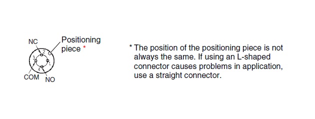
As of August 8, 2024

© Copyright OMRON Corporation 2007 - 2021. All Rights Reserved.