E2EZ-X4D1-M1J 3M
Chip-immune Inductive Proximity Sensor

Image
Anti-aluminum cut chips model proximity sensor, Sensing distance 4 mm, DC 2-wire models, NO, Pre-wired M12 connector models, 3 m
| Sensing head size |
M18 |
|---|---|
| Type |
Cylinder type (with screw), Shielded |
| Power source |
DC 2-wire models |
| Sensing distance |
4 mm ±10% |
| Setting distance |
0 to 3.2 mm |
| Operation mode |
NO |
- Ratings/Performance
As of February 5, 2024
| Sensing head size | M18 |
|---|---|
| Type | Cylinder type (with screw), Shielded |
| Power source | DC 2-wire models |
| Sensing distance | 4 mm ±10% |
| Setting distance | 0 to 3.2 mm |
| Differential distance | 20% max. of sensing distance |
| Sensing object | Ferrous metal (Sensitivity lowers with non-ferrous metals.) |
| Standard sensing object | Iron 30 x 30 x 1 mm |
| Response frequency | 100 Hz (Average value) |
| Power supply voltage | 12 to 24 VDC ripple (p-p) 10% max. |
| Operating voltage range | 10 to 30 VDC |
| Leakage current | 0.8 mA max. |
| Control output (Switching capacity) | 3 to 100 mA |
| Indicator | Operation indicator (red), Operation setting indicator (green) |
| Operation mode | NO |
| Polarity | Polarity |
| Protective circuit | Output short-cut protection Surge suppressor |
| Ambient temperature (Operating) | 0 to 50 ℃ |
| Ambient temperature (Storage) | 0 to 50 ℃ |
| Ambient humidity (Operating) | 35 to 95 % |
| Ambient humidity (Storage) | 35 to 95 % |
| Temperature influence | ±20% max. of sensing distance at 23 ℃ in the temperature range of 0 to 50 ℃ |
| Voltage influence | ±2.5% max. of sensing distance at rated voltage in the rated voltage ±10% range |
| Insulation resistance | Between charged parts and the case: 50 MΩ min. at 500 VDC |
| Dielectric strength | Between charged parts and the case: 1,000 VAC 50/60 Hz 1 min |
| Vibration resistance | Destruction: 10 to 55 Hz, 1.5 mm double amplitude each in X, Y, and Z directions for 2 h |
| Shock resistance | Destruction: 1000 m/s2 10 times each in X, Y, and Z directions |
| Degree of protection | IEC: IP67 Company standard: Oil-proof |
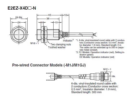
| Connection method | Pre-wired M12 connector models (3 m) |
| Weight | Package: Approx. 200 g |
| Material | Case: Brass nickel plating Sensing surface: Polybutylene terephthalate (PBT) Clamping nuts: Iron zinc plating Toothed washers: Iron zinc plating |
| Accessories | Instruction manual |
As of February 5, 2024
- Dimensions
As of February 5, 2024
Dimensions
As of February 5, 2024
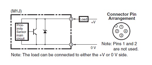
- Output circuit
As of February 5, 2024
Output circuit
Timing chart
As of February 5, 2024
- Mutual interference
As of February 5, 2024
Mutual interference
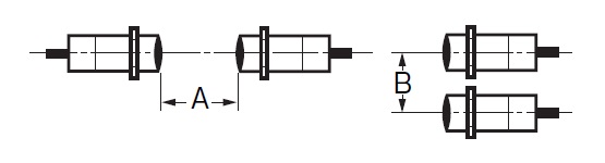
A: 40 mm min., B: 50 mm min.
As of February 5, 2024
- Effects of surrounding metals
As of February 5, 2024
Effects of surrounding metals
Iron
l: 0 mm min., dia. d: 18 mm min., D: 0 mm min., m: 16 mm min., n: 27 mm min.
Aluminum
l: 5 mm min., dia. d: 40 mm min., D: 5 mm min., m: 16 mm min., n: 54 mm min.
As of February 5, 2024
- Characteristic chart
As of February 5, 2024
Sensing distance vs. size and material of sensing object
Sensing range
As of February 5, 2024

© Copyright OMRON Corporation 2007 - 2021. All Rights Reserved.