The specifications shown in the following table apply to all the CS-series Process Analog I/O Units.
CS1W-PTS
SYSMAC CS-series Process Analog I/O Units
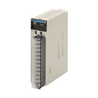
Provides the functionality of isolators, power supplies, signal converters, and other devices.
Related Contents
- Programmable Controllers
- Features
- Lineup
- Specifications
- Dimensions
- Catalog
last update: April 1, 2025
General Specifications
| Item | Specification |
|---|---|
| Applicable PLC | CS-series PLCs |
| Unit type | CS-series Special I/O Unit |
| Structure | Backplane-mounted, single slot size |
| Dimensions | 35 × 130 × 126 mm (W × H × D) |
| Weight | 450 g max. |
| External connection terminals | CS1W-PTS55/-PTS56 24-point removable terminal block (with lever) (M3 screws, Tightening torque: 0.5 Nm) Other Units 21-point removable terminal block (M3 screws, Tightening torque: 0.5 Nm) |
| Unit number switch setting | 00 to 95 |
| Self-diagnosis function | Results of self-diagnosis shown on indicators. |
| Mountable Racks | CPU Rack or CS-series Expansion Rack |
| Maximum number of Units | 80 Units (10 Units × 8 Racks) Confirm that the total current consumption of all the Units (including the CPU Unit) mounted to a single CPU Rack or Expansion Rack does not exceed the maximum power supply capacity of the Power Supply Unit. |
| Ambient operating temperature | 0 to 55 ° C |
| Ambient operating humidity | 10% to 90% (with no condensation) |
Current consumption
| Name | Model | Current consumption (power) | |
|---|---|---|---|
| 5 V | 26 V | ||
| Isolated-type Thermocouple Input Unit | CS1W-PTS01-V1 | 0.15 A (0.75 W) | 0.15 A (3.9 W) |
| CS1W-PTS11 | 0.16 A (0.60 W) | 0.08 A (2.08 W) | |
| CS1W-PTS51 | 0.25 A (1.25 W) | Not used. | |
| CS1W-PTS55 | 0.18 A (0.90 W) | 0.06 A (1.56 W) | |
| Isolated-type Resistance Thermometer Input Unit (Pt100, JPt100) | CS1W-PTS02 | 0.15 A (0.75 W) | 0.15 A (3.9 W) |
| Isolated-type Resistance Thermometer Input Unit (Ni508.4) | CS1W-PTS03 | 0.15 A (0.75 W) | 0.15 A (3.9 W) |
| Isolated-type Resistance Thermometer Input Unit (Pt100, JPt100, Pt50, Ni508.4) | CS1W-PTS12 | 0.12 A (0.60 W) | 0.07 A (1.82 W) |
| Isolated-type Resistance Thermometer Input Unit (Pt100, JPt100) | CS1W-PTS52 | 0.25 A (1.25 W) | Not used. |
| CS1W-PTS56 | 0.18 A (0.90 W) | 0.06 A (1.56 W) | |
(Reference) Maximum current and total power supplied
| Power Supply Unit | Maximum current supplied (power) | Maximum total power | ||
|---|---|---|---|---|
| 5 V | 26 V | 24 V | ||
| C200HW-PA204 | 4.6 A (23 W) | 0.6 A (15.6 W) | None | 30 W |
| C200HW-PA204C | 4.6 A (23 W) | 0.6 A (15.6 W) | None | 30 W |
| C200HW-PA204S | 4.6 A (23 W) | 0.6 A (15.6 W) | 0.8 A (19.2 W) | 30 W |
| C200HW-PA204R | 4.6 A (23 W) | 0.6 A (15.6 W) | None | 30 W |
| C200HW-PD024 | 4.6 A (23 W) | 0.6 A (15.6 W) | None | 30 W |
| C200HW-PA209R | 9 A (45 W) | 1.3 A (33.8 W) | None | 45 W |
| C200HW-PD025 | 5.3 A | 1.3 A | None | 40 W |
| CS1D-PA207R | 7 A (35 W) | 1.3 A (33.8 W) | None | 35 W |
| CS1D-PD024 | 4.3 A (21.5 W) | 0.56 A (14.6 W) | None | 28 W |
| CS1D-PD025 | 5.3 A | 1.3 A | None | 40 W |
CS1W-PTS01-V1 Isolated-type Thermocouple Input Unit
| Item | Specifications | ||
|---|---|---|---|
| Model number | CS1W-PTS01-V1 | ||
| Applicable PLC | CS Series | ||
| Unit type | CS-series Special I/O Unit | ||
| Mounting position | CS-series CPU Rack or CS-series Expansion Rack (Cannot be mounted to C200H Expansion I/O Rack or
SYSMAC BUS Remote I/O Slave Rack.) |
||
| Maximum number of
Units |
80 (within the allowable current consumption and power consumption range) | ||
| Unit numbers | 00 to 95 (Cannot duplicate Special I/O Unit numbers.) | ||
| Areas for
data exchange with CPU Unit |
Special I/O
Unit Area |
10 words/Unit
Thermometer Input Unit to CPU Unit: All process values, process value alarms (LL, L, H, HH), rate-of-change values, rate-of-change alarms (L, H), disconnection alarms, cold junction sensor errors |
|
| DM Area
words allocated to Special I/O Units |
100 words/Unit
CPU Unit to Thermocouple Input Unit: Temperature sensor type, input range (user set), scaling of process value data to be stored in allocated words in CIO area, number of items for moving average, process value alarm setting (LL, L, H, HH), rate- of-change alarm setting (L, H), zero/span adjustment value, etc. |
||
| Number of temperature
sensor inputs |
4 | ||
| Temperature sensor
types |
Thermocouple B, E, J, K, N, R, S, T or
- 80 to 80 mV. (Set separately for each of four inputs.) |
Sensor type, input range, and scaling to industrial
units are separate for each of the 4 inputs. Note: Sensor type, input range, and scaling to industrial units are set in the DM Area. |
|
| Input ranges | The input range can be set within any of the
measurable input ranges shown in Table 1 (refer to Data Sheet). Note: Internally, inputs are processed in five ranges (refer to Table 2 on Data Sheet), so accuracy and resolution accord with these internal ranges. |
Example:
Thermocouple: K; input range: 0 to 500 °C; industrial unit scaling: 0 to 500 ° C. DM Area settings are as follows: Thermocouple: 3 (0003 hex) Input signal maximum: 5000 (1388 hex) Input signal minimum: 0 (0000 hex) Industrial unit maximum value stored: 500 (01F4 hex) Industrial unit minimum value stored: 0 (0000 hex) |
|
| Scaling in industrial
units |
Data to be stored in the allocated words in the CIO
area must be scaled (with the minimum and maximum values set). Data can be stored at 0% to 100%. |
||
| Data storage in the
CIO Area |
The value derived from carrying out the following processing in order of the actual process data in the input
range is stored in four digits hexadecimal (binary values) in the allocated words in the CIO Area. 1) Mean value processing → 2) Scaling → 3) Zero/span adjustment → 4) Output limits |
||
| Accuracy (25 ° C) | ± 0.1% (of internal range full span)
As shown in the following equation, the accuracy depends on the ratio of the selected internal range (0 to 4) span to the set input range span.  |
||
| Temperature
coefficient |
± 0.015% / ° C, for any of internal range numbers 0 to 4. | ||
| Resolution | 1/4,096 (of internal range full span)
As shown in the following equation, the resolution depends on the ratio of the selected internal range (0 to 4) span to the set input range span.  |
||
| Cold junction
compensation error |
± 1 ° C, at 20 ± 10 ° C | ||
| Warmup time | 45 min | ||
| Maximum signal input | - 80 to 80 mV | ||
| Input impedance | 20 kΩ min. | ||
| Input disconnection
detection current |
0.1 μA (typical) | ||
| Response time | 1 s (travel time from input 0% to 90%, for step input) | ||
| Conversion period | 150 ms/4 inputs | ||
| Maximum time to store
data in CPU Unit |
Conversion period + one CPU Unit cycle | ||
| Disconnection
detection |
Detects disconnections at each input and turns ON the Disconnection Detection Flag.
Hardware detection time: Approx. 5 s The process value overrange direction for when a disconnection occurs can be specified. (High: 115% of set input range; low: - 15% of set input range) |
||
| Function | Mean value
processing (input filter) |
Calculates the moving average for the specified number of process values (1 to 16), and stores that value in
the CIO Area as the process value. |
|
| Process
value alarm |
Process value 4-point alarm (HH, H, LL, L), alarm hysteresis, and ON-delay timer (0 to 60 s) are available. | ||
| Rate-of-
change calculation |
Calculates the amount of change per comparison time interval (1 to 16 s). | ||
| Rate-of-
change alarm |
Rate-of-change 2-point alarm (H, L), alarm hysteresis (shared with process value alarm), and ON-delay timer
(0 to 60 s, shared with process value alarm) are available. |
||
| Isolation | Between temperature inputs and between input terminals and PLC signals: Isolation by transformer | ||
| Insulation resistance | 20 M Ω (at 500 V DC) between inputs | ||
| Dielectric strength | Between inputs: 1,000 V AC, at 50/60 Hz, for 1 min, leakage current 10 mA max. | ||
| External connections | Terminal block (detachable) | ||
| Unit number settings | Set by rotary switches on front panel, from 0 to 95. | ||
| Indicators | Three LED indicators on front panel (for normal operation, errors detected at the Thermocouple Input Unit,
and errors related to the CPU Unit). |
||
| Front panel connector | Sensor input connector terminal block (detachable) | ||
| Effect on CPU Unit cycle
time |
0.3 ms | ||
| Current consumption | 5 V DC at 150 mA max., 26 V DC at 150 mA max. | ||
| Dimensions | 35 × 130 × 126 mm (W × H × D)
Note: The height including the Backplane is 145 mm. |
||
| Weight | 450 g max. | ||
| Standard accessories | Two cold junction sensors (installed in terminal block) | ||
CS1W-PTS11 Isolated-type Thermocouple Input Unit
| Item | Specifications | |
|---|---|---|
| Model | CS1W-PTS11 | |
| Applicable PLC | CS Series | |
| Unit type | CS-series Special I/O Unit | |
| Mounting position | CS-series CPU Rack or CS-series Expansion Rack (Cannot be mounted to C200H Expansion I/O Rack or SYSMAC BUS Remote I/O Slave Rack.) |
|
|
Maximum number of Units |
80 (within the allowable current consumption and power consumption range) | |
| Unit numbers | 00 to 95 (Cannot duplicate Special I/O Unit numbers.) | |
|
Areas for data exchange with CPU Unit |
Special I/O Unit Area |
10 words/Unit Thermometer Input Unit to CPU Unit: All process values, process value alarms (LL, L, H, HH), rate-of-change values, rate-of-change alarms (L, H), disconnection alarms, cold junction sensor errors |
|
DM Area words allocated to Special I/O Units |
100 words/Unit CPU Unit to Thermocouple Input Unit: Temperature sensor type, input range (user set), scaling of process value data to be stored in allocated words in CIO area, rate-of-change input range, scaling of rate-of-change data, number of items for moving average, process value alarm setting (LL, L, H, HH), rate-of-change alarm setting (L, H), zero/span adjustment value, etc. |
|
|
Expansion Control/ Monitor Area |
35 words/Unit CPU Unit to Thermocouple Input Unit: Designations and flags for beginning or resetting the hold function selection, adjustment period control, etc. Thermocouple Input Unit to CPU Unit: Adjustment period notices (with each input), peak and bottom values, top and valley values |
|
|
Expansion Setting Area |
46 words/Unit CPU Unit to Thermocouple Input Unit: Expansion Control/Monitor Area settings, adjustment period control, peak and bottom detection, top and valley detection |
|
|
Number of temperature sensor inputs |
4 | |
|
Temperature sensor types |
The sensor type, input range, and scaling can be set individually for each of 4 inputs, which are each selectable from B, E, J, K, L, N, R, S, T, U, WRe5-26, PL II, and mV. | |
| Scaling | Data to be stored in the allocated words in the CIO area must be scaled (individually for each of the 4 inputs, with the minimum and maximum values set). Data can be stored at 0% to 100%. |
|
|
Data storage in the CIO Area |
The value derived from carrying out the following processing in order of the actual process data in the input range is stored in four digits hexadecimal (binary values) in the allocated words in the CIO Area. 1) Mean value processing → 2) Scaling → 3) Zero/span adjustment → 4) Output limits |
|
| Accuracy (25 ° C) | ± 0.05% (Depends on the Sensor used and the measured temperature. Refer to Accuracy by Sensor Type and Measured Temperature Range on Data Sheet for details.) |
|
|
Temperature coefficient |
± 0.01% / ° C (For full scale of electromotive force. See note.) | |
| Resolution | 1/64,000 | |
|
Cold junction compensation error |
± 1 ° C, at 20 ° C ± 10 ° C | |
| Warmup time | 45 min | |
| Maximum signal input | ± 120 mV | |
| Input impedance | 20 kΩ min. | |
|
Input disconnection detection current |
0.1 μA (typical) | |
| Response time | 100 ms (travel time from input 0% to 90%, for ± 100 mV step input and with moving average for 4 samples) | |
| Conversion period | 20 ms/4 inputs, 10 ms/2 inputs. Can be switched in DM Area words allocated to the Unit as a Special I/O Unit. |
|
|
Maximum time to store data in CPU Unit |
Conversion period + one CPU Unit cycle | |
|
Disconnection detection |
Detects disconnections at each input and turns ON the Disconnection Detection Flag. Hardware detection time: Approx. 0.5 s max. The process value overrange direction for when a disconnection occurs can be specified. (High: 115% of set input range; low: - 15% of set input range) |
|
| Function |
Mean value processing (input filter) |
Calculates the moving average for the specified number of process values (1 to 128), and stores that value in the CIO Area as the process value. |
|
Process value alarm |
Process value 4-point alarm (HH, H, LL, L), alarm hysteresis, and ON-delay timer (0 to 60 s) are available. | |
|
Rate-of- change calculation |
Calculates the amount of change per comparison time interval (1 to 16 s). | |
|
Rate-of- change alarm |
Rate-of-change 2-point alarm (H, L), alarm hysteresis (shared with process value alarm), and ON-delay timer (0 to 60 s, shared with process value alarm) are available. |
|
|
Adjustment period control |
When zero/span adjustment is executed, the date is internally recorded at the Unit. When the preset zero/span adjustment period and number of days notice have elapsed, this function turns ON a warning flag to give notice that it is time for readjustment. |
|
|
Peak and bottom detection |
This function detects the maximum (peak) and minimum (bottom) analog input values, from when the Hold Start Bit (output) allocated to the Expansion Control/Monitor Area turns ON until it turns OFF, and stores them in the Expansion Control/Monitor Area. |
|
|
Top and valley detection |
This function detects the top and valley values for analog inputs, from when the Hold Start Bit (output) allocated to the Expansion Control/Monitor Area turns ON until it turns OFF, and stores them in the Expansion Control/Monitor Area. |
|
| Isolation | Between inputs and PLC signals, and between inputs: Isolation by transformer for power supply, and by photocoupler for signals. |
|
| Insulation resistance | 20 M Ω (at 500 V DC) between inputs | |
| Dielectric strength | Between inputs: 1,000 V AC, at 50/60 Hz, for 1 min, leakage current 10 mA max. | |
| External connections | Terminal block (detachable) | |
| Unit number settings | Set by rotary switches on front panel, from 0 to 95. | |
| Indicators | Three LED indicators on front panel (for normal operation, errors detected at the Thermocouple Input Unit, and errors related to the CPU Unit). |
|
| Front panel connector | Sensor input connector terminal block (detachable) | |
|
Effect on CPU Unit cycle time |
0.3 ms | |
|
Current consumption (supplied from Power Supply Unit) |
5 V DC at 120 mA max., 26 V DC at 80 mA max. | |
| Dimensions | 35 × 130 × 126 mm (W × H × D) Note: The height including the Backplane is 145 mm. |
|
| Weight | 450 g max. | |
| Standard accessories | Two cold junction sensors (mounted to terminal block) | |
Note: The method for calculating the error in temperature measurements, including the temperature coefficient, is given
below. The "full scale of electromotive force" is the difference between the high limit and low limit converted to
electromotive force for each thermocouple.
below. The "full scale of electromotive force" is the difference between the high limit and low limit converted to
electromotive force for each thermocouple.
CS1W-PTS51 Isolated-type Thermocouple Input Unit
| Item | Specifications | |
|---|---|---|
| Model | CS1W-PTS51 | |
| Applicable PLC | CS Series | |
| Unit type | CS-series Special I/O Unit | |
| Mounting position | CS-series CPU Rack or CS-series Expansion Rack (Cannot be mounted to C200H Expansion I/O Rack or SYSMAC BUS Remote I/O Slave Rack.) |
|
|
Maximum number of Units |
80 (within the allowable current consumption and power consumption range) | |
| Unit numbers | 00 to 95 (Cannot duplicate Special I/O Unit numbers.) | |
|
Areas for data exchange with CPU Unit |
Special I/O Unit Area |
10 words/Unit Isolated-type Thermocouple Input Unit to CPU Unit: All process values, process value alarms (L, H), conversion data enabled flags, sensor errors, cold junction sensor errors |
|
DM Area words allocated to Special I/O Units |
100 words/Unit CPU Unit to Isolated-type Thermocouple Input Unit: Temperature sensor type, input range (user set), process value alarm setting (L, H), zero/span adjustment value. |
|
|
Number of temperature sensor inputs |
4 | |
| Temperature sensor types | The sensor type be set individually for each of 4 inputs, which are each selectable from K, J, L, R, S, T, B. | |
|
Data storage in the CIO Area |
The actual process data in the input range is stored in four digits hexadecimal (binary or BCD values) in the allocated words in the CIO Area. |
|
|
Accuracy (25 °C) (See note.) |
With Celsius selected: ± 0.3% of PV or ± 1 ° C, whichever is greater, ± 1 digit max. With fahrenheit selected: ± 0.3% of PV or ± 2 ° F, whichever is greater, ± 1 digit max. However, the accuracy of K and T at - 100 ° C or lower and L is ± 2 ° C ± 1 digit max. The accuracy of R and S at 200°C or lower is ± 3 ° C ± 1 digit max. The accuracy of B at 400 ° C or lower is not specified. PV: Process value data |
|
|
Temperature characteristic |
Refer to Temperature Characteristics According to Thermocouple Type on Data Sheet. | |
| Warmup time | 30 min | |
| Conversion period | 250 ms/4 inputs. | |
|
Maximum time to store data in CPU Unit |
Conversion period + one CPU Unit cycle | |
| Sensor error detection | Detects sensor error at each input and turns ON the Sensor error Flag. Hardware detection time: Approx. 0.5 s max. The process value overrange direction for when a sensor error occurs can be specified. (High: Set input range +20 ° C or +20 °F; low: Set input range - 20 °C or - 20 °F) |
|
| Functions |
Process value alarm |
Process value 2-point alarm (HH, H, LL, L), alarm hysteresis, and ON-delay timer (0 to 60 s) are available. External alarm outputs: One per input (H or L). |
|
External alarm outputs |
NPN outputs (with short-circuit protection) External power supply voltage: 20.4 to 26.4 V DC Max. switching capacity: 100 mA (for one output) Leakage current: 0.3 mA max. Residual voltage: 3 V max. |
|
| Isolation | Between inputs and PLC signals: Transformer for power supply and photocoupler for signals. Between each input: Transformer for power supply and photocoupler for signals. |
|
| Insulation resistance | 20 M Ω max. (at 500 V DC). Between all output and NC terminals and external AC terminals (Power Supply Unit) Between all input terminals and external AC terminals (Power Supply Unit) Between all input terminals and all output terminals Between all external DC terminals (input, output, and NC terminals) and FG plate Between all input and output terminals and all NC terminals |
|
| Dielectric strength | Between all output and NC terminals and external AC terminals (Power Supply Unit) 2,000 VAC, 50/60 Hz 1 min., detection current: 1 mA Between all input terminals and external AC terminals (Power Supply Unit) Between all input terminals and all output terminals Between all external DC terminals (input, output, and NC terminals) and FG plate 1,000 VAC, 50/60 Hz 1 min., detection current: 1 mA Between all channels 500 VAC, 50/60 Hz 1 min., detection current: 1 mA |
|
| External connections | Terminal block (detachable) | |
| Unit number settings | Set by rotary switches on front panel, from 0 to 95. | |
| Indicators | Seven LED indicators on front panel (for normal operation, errors detected at the Thermocouple Input Unit, errors related to the CPU Unit, and four indicators for external alarm outputs.) |
|
|
Effect on CPU Unit cycle time |
0.4 ms | |
|
Current consumption (supplied from Power Supply Unit) |
5 V DC at 250 mA max. | |
| Dimensions | 35 × 130 × 126 mm (W × H × D) Note: The height including the Backplane is 145 mm. |
|
| Weight | 450 g max. | |
Note: The heat generated by a Unit will dramatically change the accuracy specifications when more than one C200HW-
PA209R or CS1W-ID291 Unit is mounted side-by-side.
The following accuracy specifications apply under such conditions.
With Celsius selected:
±0.3% of PV or ±1.3°C, whichever is greater, ±1 digit max.
With Fahrenheit selected: ±0.3% of PV or ±3°F, whichever is greater, ±1 digit max.
However, the accuracy of K and T at −100°C or less and L is ±3°C ±1 digit max. The accuracy of R and S at
200°C or less is ±4°C ±1 digit max.
The accuracy of B at 400°C or less is not specified.
CS1W-PTS55 Isolated-type Thermocouple Input Unit
| Item | Specifications | |
|---|---|---|
| Model | CS1W-PTS55 | |
| Applicable PLC | CS Series | |
| Unit type | CS-series Special I/O Unit | |
| Mounting position | CS-series CPU Rack or CS-series Expansion Rack (Cannot be mounted to C200H Expansion I/O Rack or SYSMAC BUS Remote I/O Slave Rack.) |
|
|
Maximum number of Units |
80 (within the allowable current consumption and power consumption range) | |
| Unit numbers | 00 to 95 (Cannot duplicate Special I/O Unit numbers.) | |
|
Areas for data exchange with CPU Unit |
Special I/O Unit Area |
10 words/Unit Isolated-type Thermocouple Input Unit to CPU Unit: All process values, process value alarms (L, H), conversion data enabled flags, sensor errors, cold junction sensor errors |
|
DM Area words allocated to Special I/O Units |
100 words/Unit CPU Unit to Isolated-type Thermocouple Input Unit: Temperature sensor type, input range (user set), process value alarm setting (L, H), zero/span adjustment value. |
|
|
Expansion Setting Area |
1 word/Unit CPU Unit to Isolated-type Thermocouple Input Unit: Process Value Alarm |
|
|
Number of temperature sensor inputs |
8 | |
|
Temperature sensor types |
The sensor type be set individually for each of 8 inputs, which are each selectable from K, J, L, R, S, T, B ("Not used" can be selected). |
|
|
Data storage in the CIO Area |
The actual process data in the input range is stored in four digits hexadecimal (binary or BCD values) in the allocated words in the CIO Area. |
|
| Accuracy (25 ° C) | With Celsius selected: ± 0.3% of PV or ± 1 ° C, whichever is greater, ± 1 digit max. With fahrenheit selected: ± 0.3% of PV or ± 2 ° F, whichever is greater, ± 1 digit max. However, the accuracy of K and T at - 100 ° C or lower and L is ± 2 ° C ± 1 digit max. The accuracy of R and S at 200 ° C or lower is ± 3 ° C ± 1 digit max. The accuracy of B at 400°C or lower is not specified. PV: Process value data |
|
|
Temperature characteristic |
Refer to Temperature Characteristics According to Thermocouple Type on Data Sheet. | |
| Warmup time | 30 min | |
| Conversion period | 250 ms/8 inputs. | |
|
Maximum time to store data in CPU Unit |
Conversion period + one CPU Unit cycle | |
| Sensor error detection | Detects sensor error at each input and turns ON the Sensor error Flag. Hardware detection time: Approx. 0.5 s max. The process value overrange direction for when a sensor error occurs can be specified. (High: Set input range +20 ° C or +20 ° F; low: Set input range - 20 ° C or - 20 ° F) |
|
| Functions |
Process value alarm |
Process value 2-point alarm (H, L), alarm hysteresis, and ON-delay timer (0 to 60 s) are available. Two alarms per input (H, L) can be output to addresses in the CIO Area specified in the Expansion Setting Area. |
| Isolation | Between inputs and PLC signals: Transformer for power supply and photocoupler for signals. Between each input: Transformer for power supply and photocoupler for signals. |
|
| Insulation resistance | 20 M Ω max. (at 500 V DC). Between all input terminals and external AC terminals (Power Supply Unit) Between all external DC terminals (input and NC terminals) and FG plate Between all input and all NC terminals |
|
| Dielectric strength | Between NC terminals and external AC terminals (Power Supply Unit) 2,000 VAC, 50/60 Hz 1 min., detection current: 1 mA Between all input terminals and external AC terminals (Power Supply Unit) Between all external DC terminals (input and NC terminals) and FG plate 1000 VAC, 50/60 Hz 1 min., detection current: 1 mA Between all channels 500 VAC, 50/60 Hz 1 min., detection current: 1 mA |
|
| External connections | Terminal block (detachable) | |
| Unit number settings | Set by rotary switches on front panel, from 0 to 95. | |
| Indicators | Three LED indicators on front panel (for normal operation, errors detected at the Unit, errors related to the CPU Unit) |
|
|
Effect on CPU Unit cycle time |
0.4 ms | |
|
Current consumption (supplied from Power Supply Unit) |
5 V DC at 180 mA max. 26 V DC at 60 mA max. |
|
| Dimensions | 35 × 130 × 126 mm (W × H × D) Note: The height including the Backplane is 145 mm. |
|
| Weight | 450 g max. | |
CS1W-PTS02 Isolated-type Resistance Thermometer Input Unit (Pt100 or JPt100)
* Product no longer available to order.
| Item | Specifications | ||
|---|---|---|---|
| Model | CS1W-PTS02 | ||
| Applicable PLC | CS Series | ||
| Unit type | CS-series Special I/O Unit | ||
| Mounting position | CS-series CPU Rack or CS-series Expansion Rack (Cannot be mounted to C200H Expansion I/O Rack or
SYSMAC BUS Remote I/O Slave Rack.) |
||
| Maximum number of
Units |
80 (within the allowable current consumption and power consumption range) | ||
| Unit numbers | 00 to 95 (Cannot duplicate Special I/O Unit numbers.) | ||
| Areas for
data exchange with CPU Unit |
Special I/O
Unit Area |
10 words/Unit
Resistance Thermometer Input Unit to CPU Unit: All process values, process value alarms (LL, L, H, HH), rate-of-change values, rate-of-change alarms (L, H), disconnection alarms, cold junction sensor errors |
|
| DM Area
words allocated to Special I/O Units |
100 words/Unit
CPU Unit to Resistance Thermometer Input Unit: Temperature sensor type, input range (user set), scaling of process value data to be stored in allocated words in CIO area, number of items for moving average, process value alarm setting (LL, L, H, HH), rate- of-change alarm setting (L, H), zero/span adjustment value, etc. |
||
| Number of temperature
sensor inputs |
4 | ||
| Temperature sensor
types |
Pt100 (JIS, IEC) or JPt100 | Sensor type, input range, and scaling to industrial
units are separate for each of the 4 inputs. Note: Sensor type, input range, and scaling to industrial units are set in the DM Area. |
|
| Input ranges | The input range can be set within any of the
measurable input ranges shown in Table 1 (refer to Data Sheet). Note: Internally, inputs are processed in five ranges (refer to Table 2 on Data Sheet), so accuracy and resolution accord with these internal ranges. |
Example:
Sensor type: Pt100; input range: 0 to 500 °C; industrial unit scaling: 0.0 to 500 °C. DM Area settings are as follows: Sensor type: 0 (0000 hex) Input signal maximum: 5000 (1388 hex) Input signal minimum: 0 (0000 hex) Industrial unit maximum value stored: 500 (01F4 hex) Industrial unit minimum value stored: 0 (0000 hex) |
|
| Scaling in industrial
units |
Data to be stored in the allocated words in the CIO
area must be scaled (individually for each of 4 inputs, with the minimum and maximum values set). Data can be stored at 0% to 100%. |
||
| Data storage in the CIO
Area |
The value derived from carrying out the following processing in order of the actual process data in the input
range is stored in four digits hexadecimal (binary values) in the allocated words in the CIO Area. 1) Mean value processing → 2) Scaling → 3) Zero/span adjustment → 4) Output limits |
||
| Accuracy (25 ° C) | The greater of the following: ± 0.1% (of internal range full span) or 0.1 ° C
As shown in the following equation, the accuracy depends on the ratio of the selected internal range (0 to 4) span to the set input range span.  |
||
| Temperature coefficient | ± 0.015% / ° C, for any of internal range numbers 0 to 4. | ||
| Resolution | 1/4,096 (of internal range full span)
As shown in the following equation, the resolution depends on the ratio of the selected internal range (0 to 4) span to the set input range span.  |
||
| Sensing method | 3-wire method | ||
| Allowable lead wire
resistance |
20 Ω max. per wire | ||
| Input detection current | 0.25 mA | ||
| Warmup time | 10 min | ||
| Response time | 0.5 s (travel time from input 0% to 90%, for step input) | ||
| Conversion period | 100 ms/4 inputs | ||
| Maximum time to store
data in CPU Unit |
Conversion period + one CPU Unit cycle | ||
| Disconnection detection | Detects disconnections at each input and turns ON the Disconnection Detection Flag.
Hardware detection time: Approx. 1 s The process value overrange direction for when a disconnection occurs can be specified. (High: 115% of set input range; low: - 15% of set input range) |
||
| Function | Mean value
processing (input filter) |
Calculates the moving average for the specified number of process values (1 to 16), and stores that value
in the CIO Area as the process value. |
|
| Process
value alarm |
Process value 4-point alarm (HH, H, LL, L), alarm hysteresis, and ON-delay timer (0 to 60 s) are available. | ||
| Rate-of-
change calculation |
Calculates the amount of change per comparison time interval (1 to 16 s). | ||
| Rate-of-
change alarm |
Rate-of-change 2-point alarm (H, L), alarm hysteresis (shared with process value alarm), and ON-delay
timer (0 to 60 s, shared with process value alarm) are available. |
||
| Isolation | Between temperature inputs and between input terminals and PLC signals: Isolation by transformer | ||
| Insulation resistance | 20 M Ω (at 500 V DC) between inputs | ||
| Dielectric strength | Between inputs: 1,000 V AC, at 50/60 Hz, for 1 min, leakage current 10 mA max. | ||
| External connections | Terminal block (detachable) | ||
| Unit number settings | Set by rotary switches on front panel, from 0 to 95. | ||
| Indicators | Three LED indicators on front panel (for normal operation, errors detected at the Resistance
Thermometer Input Unit, and errors related to the CPU Unit). |
||
| Front panel connector | Sensor input connector terminal block (detachable) | ||
| Effect on CPU Unit cycle
time |
0.3 ms | ||
| Current consumption | 5 V DC at 150 mA max., 26 V DC at 150 mA max. | ||
| Dimensions | 35 × 130 × 126 mm (W × H × D)
Note: The height including the Backplane is 145 mm. |
||
| Weight | 450 g max. | ||
| Standard accessories | None | ||
CS1W-PTS03 Isolated-type Resistance Thermometer Input Unit (Ni508.4)
| Item | Specifications | ||
|---|---|---|---|
| Model | CS1W-PTS03 | ||
| Applicable PLC | CS Series | ||
| Unit type | CS-series Special I/O Unit | ||
| Mounting position | CS-series CPU Rack or CS-series Expansion Rack (Cannot be mounted to C200H Expansion I/O Rack or
SYSMAC BUS Remote I/O Slave Rack.) |
||
| Maximum number of
Units |
80 (within the allowable current consumption and power consumption range) | ||
| Unit numbers | 00 to 95 (Cannot duplicate Special I/O Unit numbers.) | ||
| Areas for
data exchange with CPU Unit |
Special I/O
Unit Area |
10 words/Unit
Resistance Thermometer Input Unit to CPU Unit: All process values, process value alarms (LL, L, H, HH), rate-of-change values, rate-of-change alarms (L, H), disconnection alarms |
|
| DM Area
words allocated to Special I/O Units |
100 words/Unit
CPU Unit to Resistance Thermometer Input Unit: Temperature sensor type, input range (user set), scaling of process value data to be stored in allocated ords in CIO area, number of items for moving average, process value alarm setting (LL, L, H, HH), rate- of-change alarm setting (L, H), zero/span adjustment value, etc. |
||
| Number of temperature
sensor inputs |
4 | ||
| Temperature sensor
types |
Ni508.4 | Input range and scaling to industrial units are
separate for each of the 4 inputs. Note: Sensor type, input range, and scaling to industrial units are set in the DM Area. |
|
| Input ranges | The input range can be set within a range of -50 to
150 ° C (variable setting). Note: Internally, inputs are processed in the above range (refer to Table 2 below), so accuracy and resolution accord with this internal range. |
Example:
Input range: - 50 to 100 °C; industrial unit scaling: - 50.0 to 100.0 °C. DM Area settings are as follows: Input signal maximum: 1000 (03E8 hex) Input signal minimum: - 500 (FE0C hex) Industrial unit maximum value stored: 1000 (03E8 hex) Industrial unit minimum value stored: - 500 (FE0C hex) |
|
| Scaling in industrial units | Data to be stored in the allocated words in the CIO
area must be scaled (with the minimum and maximum values set). Data can be stored at 0% to 100%. |
||
| Data storage in the
CIO Area |
The value derived from carrying out the following processing in order of the actual process data in the input
range is stored in four digits hexadecimal (binary values) in the allocated words in the CIO Area. 1) Mean value processing → 2) Scaling → 3) Zero/span adjustment → 4) Output limits |
||
| Accuracy (25 ° C) | The greater of the following: ± 0.2% (of internal range full span) or 0.2 °C
As shown in the following equation, the accuracy depends on the ratio of the selected internal range (0 to 4) span to the set input range span.  |
||
| Temperature coefficient | ± 0.015% / ° C, for any of internal range numbers 0 to 4. | ||
| Resolution | 1/4,096 (of internal range full span)
As shown in the following equation, the resolution depends on the ratio of the internal range span to the set input range span.  |
||
| Sensing method | 3-wire method | ||
| Allowable lead wire
resistance |
20 Ω max. per wire | ||
| Input detection current | 0.25 mA | ||
| Warmup time | 10 min | ||
| Response time | 0.5 s (travel time from input 0% to 90%, for step input) | ||
| Conversion period | 100 ms/4 inputs | ||
| Maximum time to store
data in CPU Unit |
Conversion period + one CPU Unit cycle | ||
| Disconnection detection | Detects disconnections at each input and turns ON the Disconnection Detection Flag.
Hardware detection time: Approx. 1 s The process value high/low direction for when a disconnection occurs can be specified. (High: 115% of set input range; low: - 15% of set input range) |
||
| Function | Mean value
processing (input filter) |
Calculates the moving average for the specified number of process values (1 to 16), and stores that value
in the CIO Area as the process value. |
|
| Process
value alarm |
Process value 4-point alarm (HH, H, LL, L), alarm hysteresis, and ON-delay timer (0 to 60 s) are available. | ||
| Rate-of-
change calculation |
Calculates the amount of change per comparison time interval (1 to 16 s). | ||
| Rate-of-
change alarm |
Rate-of-change 2-point alarm (H, L), alarm hysteresis (shared with process value alarm), and ON-delay
timer (0 to 60 s, shared with process value alarm) are available. |
||
| Isolation | Between temperature inputs and between input terminals and PLC signals: Isolation by transformer | ||
| Insulation resistance | 20 M Ω (at 500 V DC) between inputs | ||
| Dielectric strength | Between inputs: 1,000 V AC, at 50/60 Hz, for 1 min, leakage current 10 mA max. | ||
| External connections | Terminal block (detachable) | ||
| Unit number settings | Set by rotary switches on front panel, from 0 to 95. | ||
| Indicators | Three LED indicators on front panel (for normal operation, errors detected at the Resistance Thermometer
Input Unit, and errors related to the CPU Unit). |
||
| Front panel connector | Sensor input connector terminal block (detachable) | ||
| Effect on CPU Unit cycle
time |
0.3 ms | ||
| Current consumption | 5 V DC at 150 mA max., 26 V DC at 150 mA max. | ||
| Dimensions | 35 × 130 × 126 mm (W × H × D)
Note: The height including the Backplane is 145 mm. |
||
| Weight | 450 g max. | ||
| Standard accessories | None | ||
CS1W-PTS12 Isolated-type Resistance Thermometer Input Unit (Pt100, JPt100, Pt50, Ni508.4)
| Item | Specifications | |
|---|---|---|
| Model | CS1W-PTS12 | |
| Applicable PLC | CS Series | |
| Unit type | CS-series Special I/O Unit | |
| Mounting position | CS-series CPU Rack or CS-series Expansion Rack (Cannot be mounted to C200H Expansion I/O Rack or SYSMAC BUS Remote I/O Slave Rack.) |
|
|
Maximum number of Units |
80 (within the allowable current consumption and power consumption range) | |
| Unit numbers | 00 to 95 (Cannot duplicate Special I/O Unit numbers.) | |
|
Areas for data exchange with CPU Unit |
Special I/O Unit Area |
10 words/Unit Resistance Thermometer Input Unit to CPU Unit: All process values, process value alarms (LL, L, H, HH), rate-of-change values, rate-of-change alarms (L, H), disconnection alarms, adjustment period end/notices. |
|
DM Area words allocated to Special I/O Units |
100 words/Unit CPU Unit to Resistance Thermometer Input Unit: Temperature sensor type, input range (user set), scaling of process value data to be stored in allocated words in CIO area, rate-of-change input range, scaling of rate-of-change data, number of items for moving average, process value alarm setting (LL, L, H, HH), rate-of-change alarm setting (L, H), zero/ span adjustment value. |
|
|
Expansion Control/ Monitor Area words |
35 words/Unit CPU Unit to Resistance Thermometer Input Unit: Hold function selection start/reset, adjustment period control, control bits Resistance Thermometer Input Unit to CPU Unit: Adjustment period warnings/notices, peak and bottom values, top and valley values |
|
|
Expansion Setting Area words |
46 words/Unit CPU Unit to Resistance Thermometer Input Unit: Expansion Setting Area settings, adjustment period control, peak and bottom detection, top and valley detection |
|
|
Number of temperature sensor inputs |
4 | |
|
Temperature sensor type |
Pt100 (JIS, IEC), JPt100, Pt50, Ni508.4 Sensor type, input range, and scaling to industrial units are separate for each of the 4 inputs. |
|
| Scaling | Data to be stored in the allocated words in the CIO area must be scaled (with the minimum and maximum values set by user) (4 inputs set separately.). Data can be stored at 0% to 100%. |
|
|
Data storage in the CIO Area |
The value derived from carrying out the following processing in order of the actual process data in the input range is stored in four digits hexadecimal (binary values) in the allocated words in the CIO Area. 1) Mean value processing → 2) Scaling → 3) Zero/span adjustment → 4) Output limits |
|
| Accuracy (25 ° C) | The greater of the following: ± 0.05% or ± 0.1 ° C | |
|
Temperature coefficient |
Pt100: 0.009%/ ° C JPt100: 0.01%/ ° C Pt50: 0.02%/ ° C Ni508.4: 0.012%/ ° C |
|
| Resolution | 1/64,000 | |
| Sensing method | 3-wire method | |
|
Allowable lead wire resistance |
20 Ω max. per wire | |
| Input detection current | 0.5 mA | |
| Warmup time | 10 min | |
| Response time | 100 ms (travel time from input 0% to 90%, for step input and with moving average for 4 samples) | |
| Conversion period | 20 ms/4 inputs or 10 ms/2 inputs, selectable in DM Area words allocated to Unit as a Special I/O Unit. | |
|
Maximum time to store data in CPU Unit |
Conversion period + one CPU Unit cycle | |
| Disconnection detection | Detects disconnections at each input and turns ON the Disconnection Detection Flag. Hardware detection time: Approx. 0.5 s max. The process value overrange direction for when a disconnection occurs can be specified. (High: 115% of set input range; low: - 15% of set input range) |
|
| Function |
Mean value processing (input filter) |
Calculates the moving average for the specified number of process values (1 to 128), and stores that value in the CIO Area as the process value. |
|
Process value alarm |
Process value 4-point alarm (HH, H, LL, L), alarm hysteresis, and ON-delay timer (0 to 60 s are available). | |
|
Rate-of- change calculation |
Calculates the amount of change per comparison time interval (1 to 16 s). | |
|
Rate-of- change alarm |
Rate-of-change 2-point alarm (H, L), alarm hysteresis, and ON-delay timer (0 to 60 s are available, shared with process value alarm). |
|
|
Adjustment period control |
When zero/span adjustment is executed, the date is internally recorded at the Unit. When the preset zero/span adjustment period and the notice of days remaining have elapsed, this function turns ON a warning flag to give notice that it is time for readjustment. |
|
|
Peak and bottom detection |
Detects the maximum (peak) and minimum (bottom) analog input values, from when the Hold Start Bit (output) allocated to the Expansion Control/Monitor Area turns ON until it turns OFF. These values are stored as the peak and bottom values in the Expansion Control/Monitor Area. |
|
|
Top and valley detection |
This function detects the top and valley values for analog inputs, from when the Hold Start Bit (output) allocated to the Expansion Control/Monitor Area turns ON until it turns OFF. These values are stored as the top and valley values in the Expansion Control/Monitor Area. |
|
| Isolation | Between temperature inputs and between input terminals and PLC signals: Power supply isolated by transformers, signals isolated by photocouplers. |
|
| Insulation resistance | 20 M Ω (at 500 V DC) between inputs | |
| Dielectric strength | Between inputs: 1,000 V AC, at 50/60 Hz, for 1 min, leakage current 10 mA max. | |
| External connections | Terminal block (detachable) | |
| Unit number settings | Set by rotary switches on front panel, from 0 to 95. | |
| Indicators | Three LED indicators on front panel (for normal operation, errors detected at the Resistance Thermometer Input Unit, and errors detected at the CPU Unit). |
|
| Front panel connector | Sensor input connector terminal block (detachable) | |
|
Effect on CPU Unit cycle time |
0.3 ms | |
| Current consumption | 5 V DC at 120 mA max., 26 V DC at 70 mA max. | |
| Dimensions | 35 × 130 × 126 mm (W × H × D) Note: The height including the Backplane is 145 mm. |
|
| Weight | 450 g max. | |
| Standard accessories | None | |
CS1W-PTS52 Isolated-type Resistance Thermometer Input Unit (Pt100, JPt100)
| Item | Specifications | |
|---|---|---|
| Model | CS1W-PTS52 | |
| Applicable PLC | CS Series | |
| Unit type | CS-series Special I/O Unit | |
| Mounting position | CS-series CPU Rack or CS-series Expansion Rack (Cannot be mounted to C200H Expansion I/O Rack or SYSMAC BUS Remote I/O Slave Rack.) |
|
|
Maximum number of Units |
80 (within the allowable current consumption and power consumption range) | |
| Unit numbers | 00 to 95 (Cannot duplicate Special I/O Unit numbers.) | |
|
Areas for data exchange with CPU Unit |
Special I/O Unit Area |
10 words/Unit Resistance Thermometer Input Unit to CPU Unit: All process values, process value alarms (L, H), conversion data enabled flag, sensor errors. |
|
DM Area words allocated to Special I/O Units |
100 words/Unit CPU Unit to Resistance Thermometer Input Unit: Temperature sensor type, input range (user set), process value alarm setting (L, H), zero/span adjustment value. |
|
|
Number of temperature sensor inputs |
4 | |
|
Temperature sensor type |
Pt100 (JIS, IEC), JPt100 The same sensor type, input range, and scaling to industrial units are used by all inputs. |
|
|
Data storage in the CIO Area |
The actual process data in the input range is stored in four digits hexadecimal (binary or BCD values) in the allocated words in the CIO Area. |
|
| Accuracy (25 ° C) | ± 0.3% of PV or ± 0.8 ° C, whichever is greater, ± 1 digit max. ( ± 0.3% of PV or ± 1.6 ° F, whichever is greater, ± 1 digit max.) PV: Process value data |
|
|
Temperature characteristics |
Refer to Temperature Characteristics According to Platinum Resistance Thermometer Type on Data Sheet. | |
| Sensing method | 3-wire method | |
| Input detection current | 1 mA | |
|
Influence of conductor resistance |
0.4 ° C/ Ω max. | |
| Conversion period | 250 ms/4 inputs | |
| Warmup time | 10 min | |
|
Maximum time to store data in CPU Unit |
Conversion period + one CPU Unit cycle | |
| Sensor error detection | Detects sensor error at each input and turns ON the Sensor error Flag. Hardware detection time: Approx. 0.5 s max. The process value overrange direction for when a sensor error occurs can be specified. (High: +20 digit of set input range; low: - 20 digit of set input range) |
|
| Function |
Process value alarm |
Process value 2-point alarm (H, L), alarm hysteresis, and ON-delay timer (0 to 60 s are available). |
|
External alarm outputs |
NPN outputs (with short-circuit protection) External power supply voltage: 20.4 to 26.4 V DC Max. switching capacity: 100 mA (for one output) Leakage current: 0.3 mA max. Residual voltage: 3 V max. |
|
| Isolation | Between inputs and PLC signal: Transformer for power supply and photocoupler for signals Between each input: Transformer for power supply and photocoupler for signals |
|
| Insulation resistance | 20 M Ω max. (at 500 V DC). Between all output and NC terminals and external AC terminals (Power Supply Unit) Between all input terminals and external AC terminals (Power Supply Unit) Between all input terminals and all output terminals Between all external DC terminals (input, output, and NC terminals) and FG plate Between all input and output terminals and all NC terminals |
|
| Dielectric strength | Between all output and NC terminals and external AC terminals (Power Supply Unit) 2,000 V AC, 50/60 Hz 1 min., detection current: 1 mA Between all input terminals and external AC terminals (Power Supply Unit) Between all input terminals and all output terminals Between all external DC terminals (input, output, and NC terminals) and FG plate 1,000 V AC, 50/60 Hz 1 min., detection current: 1 mA Between all channels 500 VAC, 50/60 Hz 1 min., detection current: 1 mA |
|
| External connections | Terminal block (detachable) | |
| Unit number settings | Set by rotary switches on front panel, from 0 to 95. | |
| Indicators | Seven LED indicators on front panel (for normal operation, errors detected at the Unit, errors detected at the CPU Unit, and four indicators for external alarm outputs.) |
|
|
Effect on CPU Unit cycle time |
0.4 ms | |
| Current consumption | 5 V DC at 250 mA max | |
| Dimensions | 35 × 130 × 126 mm (W × H × D) Note: The height including the Backplane is 145 mm. |
|
| Weight | 450 g max. | |
CS1W-PTS56 Isolated-type Resistance Thermometer Input Unit (Pt100, JPt100)
| Item | Specifications | |
|---|---|---|
| Model | CS1W-PTS56 | |
| Applicable PLC | CS Series | |
| Unit type | CS-series Special I/O Unit | |
| Mounting position | CS-series CPU Rack or CS-series Expansion Rack (Cannot be mounted to C200H Expansion I/O Rack or SYSMAC BUS Remote I/O Slave Rack.) |
|
|
Maximum number of Units |
80 (within the allowable current consumption and power consumption range) | |
| Unit numbers | 00 to 95 (Cannot duplicate Special I/O Unit numbers.) | |
|
Areas for data exchange with CPU Unit |
Special I/O Unit Area |
10 words/Unit Resistance Thermometer Input Unit to CPU Unit: All process values, process value alarms (L, H), conversion data enabled flag, sensor errors. |
|
DM Area words allocated to Special I/O Units |
100 words/Unit CPU Unit to Resistance Thermometer Input Unit: Temperature sensor type, input range (user set), process value alarm setting (L, H), zero/span adjustment value. |
|
|
Expansion Setting Area |
1 word/Unit CPU Unit to Resistance Thermometer Input Unit: Process Value Alarm |
|
|
Number of temperature sensor inputs |
8 | |
|
Temperature sensor type |
Pt100 (JIS, IEC), JPt100 The same sensor type, input range, and scaling to industrial units are used by all inputs. |
|
|
Data storage in the CIO Area |
The actual process data in the input range is stored in four digits hexadecimal (binary or BCD values) in the allocated words in the CIO Area. |
|
| Accuracy (25 ° C) | ± 0.3% of PV or ± 0.8 ° C, whichever is greater, ± 1 digit max. ( ± 0.3% of PV or ± 1.6 ° F, whichever is greater, ± 1 digit max.) PV: Process value data |
|
|
Temperature characteristics |
Refer to Temperature Characteristics According to Platinum Resistance Thermometer Type on Data Sheet. | |
| Sensing method | 3-wire method | |
|
Influence of conductor resistance |
0.4 ° C/ Ω max. | |
| Input detection current | 0.5 mA | |
| Warmup time | 10 min | |
| Conversion period | 250 ms/8 inputs | |
|
Maximum time to store data in CPU Unit |
Conversion period + one CPU Unit cycle | |
| Sensor error detection | Detects sensor error at each input and turns ON the Sensor error Flag. Hardware detection time: Approx. 0.5 s max. The process value overrange direction for when a sensor error occurs can be specified. (High: +20 digit of set input range; low: - 20 digit of set input range) |
|
| Function |
Process value alarm |
Process value 2-point alarm (H, L), alarm hysteresis, and ON-delay timer (0 to 60 s are available). Two alarms per input (H, L) can be output to addresses in the CIO Area specified in the Expansion Setting Area. |
| Isolation | Between inputs and PLC signal: Transformer for power supply and photocoupler for signals Between each input: Transformer for power supply and photocoupler for signals |
|
| Insulation resistance | 20 M Ω max. (at 500 V DC). Between all input terminals and external AC terminals (Power Supply Unit) Between all input terminals and FG plate |
|
| Dielectric strength | Between all input terminals and external AC terminals (Power Supply Unit) Between all input terminals and FG plate 1,000 V AC, 50/60 Hz 1 min., detection current: 1 mA Between all channels 500 VAC, 50/60 Hz 1 min., detection current: 1 mA |
|
| External connections | Terminal block (detachable) | |
| Unit number settings | Set by rotary switches on front panel, from 0 to 95. | |
| Indicators | Three LED indicators on front panel (for normal operation, errors detected at the Unit, errors detected at the CPU Unit) |
|
|
Effect on CPU Unit cycle time |
0.4 ms | |
| Current consumption | 5 V DC at 180 mA max. 26 V DC at 60 mA max. |
|
| Dimensions | 35 × 130 × 126 mm (W × H × D) Note: The height including the Backplane is 145 mm. |
|
| Weight | 450 g max. | |
last update: April 1, 2025
© Copyright OMRON Corporation 2007 - 2026. All Rights Reserved.