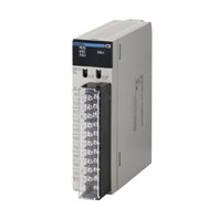
| Item | CS1W-DA041 | CS1W-DA08V | CS1W-DA08C | |
|---|---|---|---|---|
| Applicable PLC model | CS series | |||
| Unit type | CS1 Special I/O Unit | |||
| Isolation *1 | Between I/O and PLC signals: Photocoupler (No isolation between individual I/O signals.) |
|||
| External terminals | 21-point detachable terminal block (M3 screws) | |||
| Power consumption | 130 mA max. at 5 VDC, 180 mA max. at 26 VDC |
130 mA max. at 5 VDC, 180 mA max. at 26 VDC |
130 mA max. at 5 VDC, 250 mA max. at 26 VDC |
|
| Dimensions (mm) *2 | 35 × 130 × 126 (W × H × D) | |||
| Weight | 450 g max. | |||
| General specifications | Conforms to general specifications for SYSMAC CS-series Series. | |||
| Mounting position | CS-series CPU Rack or CS-series Expansion Rack (Cannot be mounted to a C200H Expansion I/O Rack or a SYSMAC BUS Slave Rack.) |
|||
| Maximum number of Units | Depends on the Power Supply Unit. *3 | |||
| Data exchange with CPU Units *4 | Special I/O Unit Area CIO 200000 to CIO 295915 (Words CIO 2000 to CIO 2959) |
|||
| Internal Special I/O Unit DM Area (D20000 to D29599) | ||||
|
Output specifications |
Number of analog outputs | 4 | 8 | 8 |
| Output signal ranges *5 | 1 to 5 V/4 to 20 mA 0 to 5 V 0 to 10 V - 10 to 10V |
1 to 5 V 0 to 5 V 0 to 10 V - 10 to 10 V |
4 to 20 mA | |
| Output impedance | 0.5 Ω max. (for voltage output) | |||
|
Max. output current (for 1 point) |
12 mA (for voltage output) | |||
|
Maximum permissible load resistance |
600 Ω (current output) *9 | --- | 600 Ω (current output) *8 | |
| Resolution | 4,000 (full scale) | |||
| Set data | 16-bit binary data | |||
| Accuracy *6 | 23 ± 2 ° C: Voltage output: ± 0.3% of full scale Current output: ± 0.5% of full scale |
|||
| 0 ° C to 55 ° C: Voltage output: ± 0.5% of full scale Current output: ± 0.8% of full scale |
||||
| D/A conversion time *7 | 1.0 ms/point max. | |||
|
Output functions |
Output hold function | Outputs the specified output status (CLR, HOLD, or MAX) under any of the following circumstances. When the Conversion Enable Bit is OFF. *8 In adjustment mode, when a value other than the output number is output during adjustment. When there is an output setting error or a fatal error occurs at the PLC. When the CPU Unit is on standby. When the Load is OFF. |
||
