Page top

H3CR-A

Solid-state Multi-functional Timers

H3CR-A

Multiple Operating Modes and Multiple Time Ranges. DIN 48 x 48-mm Multifunctional Timer.

General

Item H3CR-A/-AS/-A-301 H3CR-AP H3CR-A8/-A8S/-A8-301 H3CR-A8E
Operating mode A: ON-delay
B: Flicker OFF start
B2: Flicker ON start
C: Signal ON/OFF-delay
D: Signal OFF-delay
E: Interval
G: Signal ON/OFF-delay
J: One-shot
A: ON-delay (power supply start)
B: Flicker OFF start (power supply start)
B2: Flicker ON start (power supply start)
E: Interval (power supply start)
J: One-shot (power supply start)
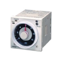
Pin type 11-pin 8-pin
Input type No-voltage input Voltage input ---
Time-limit output type H3CR-A/-A8/-AP/-A-301/-A8-301: Relay output (DPDT)
H3CR-AS/-A8S: Transistor output (NPN/PNP universal) *1
Relay output
(SPDT)
Instantaneous output type --- Relay output
(SPDT)
Mounting method DIN track mounting, surface mounting, and flush mounting
Approved standards UL508, CSA C22.2 No.14, NK, Lloyds, CCC: GB/T 14048.5 *2
Conforms to EN61812-1 and IEC60664-1 (VDE0110) 4kV/2.

*1 The internal circuits are optically isolated from the output. This enables universal application as NPN or PNP transistor.
     For details, refer to your OMRON website.
*2 CCC certification requirements

Recommended fuse Contact Output: 0216005 (250 VAC, 5 A), manufactured by Littelfuse
Transistor Output: 0216.100 (250 VAC, 100 mA) manufactured by Littelfuse
Rated operating voltage Ue
Rated operating current Ie
Contact Output:
AC-15: Ue: 250 VAC, Ie: 3 A
AC-13: Ue: 250 VAC, Ie: 5 A
DC-13: Ue: 30 VDC, Ie: 0.5 A
Transistor Output:
DC-13: Ue: 30 VDC, Ie: 0.1 A
Rated insulation voltage 250 V
Rated impulse withstand voltage
(altitude: 2,000 m max.)
4 kV (at 240 VAC)
Conditional short-circuit current 1000 A

Time Ranges

Note: When the time setting knob is turned below "0" until the point where the time setting knob stops, the output will
          operate instantaneously at all time range settings.
          For details, refer to your OMRON website.

Standard (0.05-s to 300-h) Models

Time unit s (sec) ×10 s (10 sec) min (min) ×10 min (10 min) h (hrs) ×10 h (10 hrs)
Full scale
setting
1.2 0.05 to 1.2 1.2 to 12 0.12 to 1.2 1.2 to 12 0.12 to 1.2 1.2 to 12
3 0.3 to 3 3 to 30 0.3 to 3 3 to 30 0.3 to 3 3 to 30
12 1.2 to 12 12 to 120 1.2 to 12 12 to 120 1.2 to 12 12 to 120
30 3 to 30 30 to 300 3 to 30 30 to 300 3 to 30 30 to 300

Double (0.1-s to 600-h) Models

Time unit s (sec) ×10 s (10 sec) min (min) ×10 min (10 min) h (hrs) ×10 h (10 hrs)
Full scale
setting
2.4 0.1 to 2.4 2.4 to 24 0.24 to 2.4 2.4 to 24 0.24 to 2.4 2.4 to 24
6 0.6 to 6 6 to 60 0.6 to 6 6 to 60 0.6 to 6 6 to 60
24 2.4 to 24 24 to 240 2.4 to 24 24 to 240 2.4 to 24 24 to 240
60 6 to 60 60 to 600 6 to 60 60 to 600 6 to 60 60 to 600

Ratings

Rated supply voltage
*1 *2 *5
100 to 240 VAC (50/60 Hz)/100 to 125 VDC, 24 to 48 VAC (50/60 Hz)/12 to
48 VDC (24 to 48 VAC/VDC for H3CR-A8E) *3
Operating voltage range 85% to 110% of rated voltage (90% to 110% at 12 to 48 VDC)
Power reset Minimum power-opening time: 0.1 s
Input *6 No-voltage Input
ON impedance: 1 kΩ max.
ON residual voltage: 1 V max.
OFF impedance: 100 kΩ min.
Voltage Input
Max. permissible capacitance between inputs lines (terminals 6 and 7): 1,200 pF
Load connectable in parallel with inputs (terminals 6 and 7).
100 to 240 VAC/100 to 125 VDC
High (logic) level: 85 to 264 VAC/85 to 137.5 VDC
Low (logic) level: 0 to 10 VAC/0 to 10 VDC
24 to 48 VAC/12 to 48 VDC
High (logic) level: 20.4 to 52.8 VAC/10.8 to 52.8 VDC
Low (logic) level: 0 to 2.4 VAC/0 to 1.2 VDC
Power consumption H3CR-A/-A8
100 to 240 VAC/100 to 125 VDC (When at 240 VAC, 60 Hz)
Relay ON: approx. 2.0 VA (1.6 W), Relay OFF: approx. 1.3 VA (1.1 W)
24 to 48 VAC/12 to 48 VDC (When at 24 VDC)
Relay ON: approx. 0.8 W, Relay OFF: approx. 0.2 W
H3CR-AP *3
100 to 240 VAC/100 to 125 VDC (When at 240 VAC, 60 Hz)
Relay ON: approx. 2.5 VA (2.2 W) *4, Relay OFF: approx. 1.8 VA (1.7 W) *4
24 to 48 VAC/12 to 48 VDC (When at 24 VDC)
Relay ON: approx. 0.9 W *4, Relay OFF: approx. 0.3 W *4
H3CR-A8E
100 to 240 VAC/100 to 125 VDC (When at 240 VAC, 60 Hz)
Relay ON/OFF: approx. 2 VA (0.9 W)
24 to 48 VAC/VDC (When at 24 VDC)
Relay ON/OFF: approx. 0.9 W
H3CR-AS/-A8S
24 to 48 VAC/12 to 48 VDC (When at 24 VDC)
Output ON: 0.3 W, Output OFF: 0.2 W
Control outputs Models with Contact Outputs
H3CR-A/-A8/-AP
5A at 250 VAC/30 VDC, 0.15A at 125 VDC, resistive load (cosφ = 1)
Minimum applied load: 10mA at 5 VDC (failure level: P reference value)
Contact materials: Ag-alloy
H3CR-A8E
5A at 250 VAC/30 VDC, 0.15A at 125 VDC, resistive load (cosφ = 1)
Minimum applied load: 10mA at 5 VDC (failure level: P reference value)
Contact materials: AgSnIn
Transistor output: Open collector(NPN/PNP)
H3CR-AS/-A8S
100 mA max at 30 VDC max., residual voltage: 2 VDC max.

*1. DC ripple rate: 20% max. (A single-phase, full-wave-rectification power supply can be used).
*2. Do not use an inverter output as the power supply. Refer to your OMRON website for details.
*3. Models with 24-to-48-VAC or 12-to-48-VDC power supply have inrush current. Caution is thus required when turning
       ON and OFF power to the Timer with a non-contact output from a device such as a sensor. (Models with an inrush
       current of approximately 50 mA and a 24-VDC power supply are available (the H3CR-A-302 and H3CR-A8-302).)
       For details, consult your OMRON sales representative.
*4. The values are for when the terminals 2 and 7 and terminals 10 and 6 are short-circuited, and include the
       consumption current of the input circuit.
*5. Refer to your OMRON website when using the Timer together with a 2-wire AC proximity sensor.
*6. For details, see Input Connections: No-voltage Input Signal Levels on Catalog, and Input Connections: Voltage Input
       Signal Levels on Catalog.

Characteristics

Accuracy of operating
time
±0.2% FS max. (±0.2%±10 ms max. in a range of 1.2 s or 3 s)
Setting error ±5% FS ±50 ms *1
Reset time Min. power-opening time: 0.1 s max.
Min. pulse width: 0.05 s (H3CR-A/-AS)
Reset voltage 10% max. of rated supply voltage
Influence of voltage *2 ±0.2% FS max. (±0.2%±10 ms max. in a range of 1.2 s or 3 s)
Influence of temperature ±1% FS max. (±1%±10 ms max. in a range of 1.2 s or 3 s)
Insulation resistance 100 MΩ min. (at 500 VDC)
Dielectric strength 2,000 VAC (1,000 VAC for H3CR-A[]S), 50/60 Hz for 1 min (between current-carrying
metal parts and exposed non-current-carrying metal parts)
2,000 VAC (1,000 VAC for H3CR-A[]S), 50/60 Hz for 1 min (between control output
terminals and operating circuit)
2,000 VAC, 50/60 Hz for 1 min (between contacts of different polarities)
1,000 VAC, 50/60 Hz for 1 min (between contacts not located next to each other)
2,000 VAC, 50/60 Hz for 1 min (between input and control output terminals and
operation circuit) for H3CR-AP
Impulse withstand
voltage
5 kV (between power terminals) for 100 to 240 VAC/100 to 125 VDC, 1 kV for 24 to 48
VAC/12 to 48 VDC
5 kV (between current-carrying terminal and exposed non-current-carrying metal
parts) for 100 to 240 VAC/100 to 125 VDC, 1.5 kV for 24 to 48 VAC/12 to 48 VDC and
24 to 48 VAC/VDC
Noise immunity ±1.5 kV (between power terminals) and ±600 V (between no-voltage input terminals),
square-wave noise by noise simulator (pulse width: 100 ns/1 μs, 1-ns rise)
Static immunity Malfunction: 8 kV
Destruction: 15 kV
Vibration resistance Destruction: 10 to 55 Hz with 0.75-mm single amplitude each in 3 directions for 2 hours
each
Malfunction: 10 to 55 Hz with 0.5-mm single amplitude each in 3 directions for 10
minutes each
Shock resistance Destruction: 1,000 m/s2 3 times each in 6 directions
Malfunction: 100 m/s2 3 times each in 6 directions
Ambient temperature Operating: -10°C to 55°C (with no icing)
Storage: -25°C to 65°C (with no icing)
Ambient humidity Operating: 35% to 85%
Life expectancy *4 Mechanical: 20,000,000 operations min. (under no load at 1,800 operations/h)
Electrical: 100,000 operations min. (5 A at 250 VAC, resistive load at 1,800
operations/h) *3
EMC (EMI) EN61812-1
Emission Enclosure: EN55011 Group 1 class A
Emission AC Mains: EN55011 Group 1 class A
(EMS) EN61812-1
Immunity ESD: IEC61000-4-2
Immunity RF-interference: IEC61000-4-3
Immunity Burst: IEC61000-4-4
Immunity Surge: IEC61000-4-5
Immunity Conducted Disturbance: IEC61000-4-6
Immunity Voltage Dip/Interruption: IEC61000-4-11
Case color Light gray (Munsell 5Y7/1)
Degree of protection IP40 (panel surface)
Weight Approx. 90 g

*1. The value is ±5% FS +100 ms to −0 ms max. when the C, D, or G mode signal of the H3CR-AP is OFF.
*2. The influence of voltage of the H3CR-A8E (24 to 48 VAC/12 to 48 VDC) is ±2.0% FS max. with a single-phase power
       supply with fullwave rectification.
*3. Refer to the Life-test Curve (Reference).
*4. Contact output only.

Life-test Curve (Reference)

H3CR-A Specifications 11

Reference:
A maximum current of 0.15 A can be switched at 125 VDC (cosφ = 1) and a maximum current of 0.1A can be switched at 125V DC and L/R = 7ms.
In both cases, a life of 100,000 operations can be expected.
The minimum applicable load is 10 mA at 5 VDC (failure level: P).