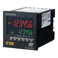
Page top

H7BX

Multifunction Counter (DIN 72 × 72)

H7BX

DIN 72×72 mm Multifunction Counter with a Bright,Easy-to-view, Negative Transmissive LCD.

Ratings

Model H7BX-A/AD1 H7BX-AW/AWD1
Type Preset counter Preset counter/tachometer
Supported configurations 1-stage preset counter, total
and preset counter *1
(selectable)
1-stage preset counter, 2-stage preset counter,
total and preset counter (*1), batch counter, dual
counter, twin counter, tachometer (selectable)
Ratings Power supply
voltage *2
H7BX-A/AW: 100 to 240 VAC (50/60 Hz)
H7BX-AD1/AWD1: 24 VAC (50/60 Hz)/12 to 24 VDC (ripple 20% max.)
Operating
voltage range
85% to 110% of rated supply voltage (90% to 110% at 12 VDC)
Power
consumption
H7BX-A/AW: 9.6 VA max. (100 to 240 VAC)
H7BX-AD1/AWD1: 8 VA max. (24 VAC), 5.3 W max. (12 to 24 VDC)
Mounting method Flush mounting
External connections Screw terminals
Degree of protection Compliant with IEC IP54 for panel surface only, Certified for UL Type 1
Input signals CP1, CP2, reset 1, reset 2, key protection
Counter Max. counting
speed
30 Hz or 5 kHz (selectable, ON/OFF ratio 1:1), setting for both CP1 and CP2
Input modes Increment (UP), decrement (DOWN), increment/decrement (UP/DOWN A (command
input), UP/DOWN B (individual inputs), or UP/DOWN C (quadrature inputs)), UP/
DOWN D (command input), UP/DOWN E (individual inputs), UP/DOWN F
(quadrature inputs)
Output modes N, F, C, R, K-1, P, Q, A, K-2, D, L N, F, C, R, K-1, P, Q, A, K-2, D, L, H
One-shot output
time
0.01 to 99.99 s
Reset input External reset (minimum reset input signal width: 1 ms or 20 ms selectable), manual
reset, and automatic reset (internal according to C, R, P, and Q mode operation)
Tachometer Pulse
measurement
method
--- Periodic measurement (Sampling period: 200 ms)
Max. counting
speed
--- 30 Hz or 10 kHz (selectable)
Measuring
ranges
--- 30 Hz: 0.01 to 30.00 Hz
10 kHz: 1-input mode: 0.001 to 10 kHz
Other modes: 0.01 to 5 kH
Measuring
accuracy
--- ±0.1% FS ±1 digit max. (at 23 ±5°C)
Output modes --- Input mode:
Not 2-input independent measurement:
Upper and lower limits, area, upper limit, lower
limit.
2-input independent measurement: Upper limit,
lower limit
Auto-zero time --- 0.1 to 999.9 s
Startup time --- 0.0 to 99.9 s
Average
processing
--- OFF/2/4/8/16 times
Prescaling function Yes (0.001 to 99.999)
Decimal point adjustment Yes (rightmost 3 digits)
Sensor waiting time 290 ms max. (Control output is turned OFF and no input is accepted during sensor
waiting time.)
Key protection input Response speed: Approx. 1 s
No-voltage NPN input (fixed)
Short-circuit (ON) impedance: 1 kΩ max. (Leakage current at 0 Ω: Approx. 12 mA)
Short-circuit (ON) residual voltage: 3 V max.
Open (OFF) impedance: 100 kΩ min.
Input method
(except key protection input)
No-voltage NPN input or voltage PNP input (selectable)
No-voltage input
Short-circuit (ON) impedance: 1 kΩ max. (Leakage current at 0 Ω: Approx. 12 mA)
Short-circuit (ON) residual voltage: 3 V max.
Open (OFF) impedance: 100 kΩ min.
Voltage input
High level: 4.5 to 30 VDC
Low level: 0 to 2 VDC
Input resistance: Approx. 4.7 kΩ
External power supply 12 VDC (±10%), 100 mA (For details, refer to External Power Supply on Data Sheet.)
Control output Contact output: 3 A at 250 VDC/30 VDC, resistive load (cosφ = 1)
Minimum applied load: 10 mA at 5 VDC (Failure level: P, reference value)
Transistor output: 100 mA max. at 30 VDC max.
Residual voltage: 1.5 VDC max. (approx. 1 V)
Leakage current: 0.1 mA max.
Display *3 Backlit 7-segment negative transmissive LCD
Character Heights
PV: 13.5 mm (red/green)
SV: 9 mm (green)
Digits 6 digits
-99,999 to 999,999 (5 digits
negative and 6 digits positive)
6 digits
Counter: -99,999 to 999,999 (5 digits negative
and 6 digits positive)
Tachometer: 0 to 999,999 (6 digits)
Memory backup Non-volatile memory (Overwrites: 100,000 min.), Data storage: 10 years min.
Ambient operating temperature -10 to 55°C (with no icing)
Ambient storage temperature -25 to 65°C (with no icing)
Ambient operating humidity 25 to 85°C (with no condensation)
Case color Black (N1.5)
Accessories Two flush-mounting adapters,
terminal cover
Two flush-mounting adapters, terminal cover,
DIP switch setting stickers

*1. The total and preset counter functions as a 1-stage preset counter and total counter.
*2. Do not use an inverter output for the power supply.
*3. Displayed only when the power is ON. Not displayed when the power is OFF.

Characteristics

Insulation resistance 100 MΩ min. (at 500 VDC) between current-carrying terminal and exposed non-current-carrying
metal parts, and between non-continuous contacts
Dielectric strength Between current-carrying metal parts and non-current-carrying metal parts: 2,000 VAC, 50/60 Hz
for 1 min
Between power supply and input circuit: 2,000 VAC, 50/60 Hz for 1 min (for models other than
the H7BX-A[]D1)
1,000 VAC, 50/60 Hz for 1 min (H7BX-A[]D1)
Between control output, power supply, and input circuit: 2,000 VAC, 50/60 Hz for 1 min
Between non-continuous contacts: 1,000 VAC, 50/60 Hz for 1 min
Impulse withstand
voltage
6.0 kV between power terminals:
3.0 kV (1.0 kV for 24 VAC/12 to 24 VDC models)
6.0 kV between current-carrying terminal and exposed non-current-carrying metal parts:
4.5 kV (1.5 kV for 24 VAC/12 to 24 VDC models)
Noise immunity Between power terminals: ±1.5 kV
Between input terminals: ±600 V
Square-wave noise by noise simulator (Pulse width: 100 ns/1 μs, 1-ns rise)
Static immunity Malfunction: 8 kV
Destruction: 15 kV
Vibration resistance Destruction: 10 to 55 Hz, 0.75-mm single amplitude, 2 hours each in three directions
Malfunction: 10 to 55 Hz, 0.50-mm single amplitude, 10 minutes each in three directions
Shock resistance Destruction: 294 m/s2 3 times each in 6 directions
Malfunction: 98 m/s2 3 times each in 6 directions
Life expectancy Mechanical: 10,000,000 operations min.
Electrical: 100,000 operations min. (3 A at 250 VAC/30 VDC, resistive load) *
Weight Approx. 250 g

* Check the electrical life expectancy curve.

Electrical Life Expectancy (Reference Values)

Resistive Load

H7BX Specifications 6

Inductive Load

H7BX Specifications 7

A current of 0.15 A max. can be switched at 125 VDC (cosφ = 1) and current of 0.1 A max. can be switched with L/R = 7 m/s. In both cases, a life of 100,000 operations can be expected.

Applicable Standards

Approved
safety
standards
cURus: UL 508, CSA C22.2 No. 14
EN 61010-1 (IEC 61010-1): Pollution degree 2/overvoltage category II;
EN 61326; VDE 0106 Part 100
EMC (EMI) EN 61326-1 *
Emission Enclosure: EN 55011 Group 1 class A
Emission AC mains: EN 55011 Group 1 class A
(EMS) EN 61326-1 *
Immunity ESD: EN 61000-4-2: 4 kV contact discharge; 8 kV air discharge
Immunity RF-interference: EN 61000-4-3: 10 V/m (Amplitude-modulated, 80 MHz to 1 GHz); 10 V/m (Pulse-
modulated, 900 MHz ±5 MHz)
Immunity Conducted Disturbance: EN 61000-4-6: 3 V (0.15 to 80 MHz)
Immunity Burst: EN 61000-4-4: 2 kV power-line; 1 kV I/O signal-line
Immunity Surge: EN 61000-4-5: 1 kV line to lines (power and output lines (relay outputs)); 2 kV line to
ground (power and output lines (relay outputs))
Immunity Voltage Dip/Interruption: EN 61000-4-11: Voltage Dip, 1 cycle, 100% (rated voltage), 10/12 cycle
60% (rated voltage), 25/30 cycle 30% (rated voltage), Interruption, 250/300 cycle 100% (rated voltage)

* Industrial electromagnetic environment (EN/IEC 61326-1 Table 2)

I/O Functions

Using as a Counter *1

Inputs CP1, CP2 (1) All Modes Except for Dual Counter Mode and Twin Counter Mode
• Reads count signals.
• Increment, decrement, up/down (command, individual, or quadrature) inputs can be used.
(2) Dual Counter Mode or Twin Counter Mode
• Reads CP1 count signals on CP1 input and CP2 count signals on CP2 input.
• Increment signals can be used.
Reset or
Reset 1
(1) All Modes Except for Dual Counter Mode and Twin Counter Mode
• Resets present value and outputs (OUT2 when using the batch counter). *2
• Counting cannot be performed while resetting or when reset 1 input is ON.
• The reset indicator is lit while the reset input is ON.
(2) Dual Counter Mode or Twin Counter Mode
• Resets the CP1 present value to 0.
• Counting the CP1 input cannot be performed while the reset 1 input is ON.
• The reset indicator is lit while the reset 1 input is ON.
Total Reset
or Reset 2
The reset operation depends on the selected function. *3
Outputs OUT1, 2 When the corresponding set value is reached, signals are output according to the designated
output mode.

*1. Refer to Data Sheet for information on the operation of input and output functions.
*2. In increment mode or increment/decrement mode, the present value returns to 0; in decrement mode, the present
       value returns to the set value with 1-stage models, and returns to set value 2 with 2-stage models.
*3. The reset indicator will not be lit when the total reset or reset 2 input is ON.

Function Reset operation
1-stage/2-stage preset
counter
Does not operate (Not used).
Total and preset counter • Resets the total count value.
• Holds the total count value at 0 while the total reset input is ON.
Batch counter • Resets the batch count value and batch output (OUT1).
• Holds the batch count value at 0 while the reset 2 input is ON.
Dual counter • Resets the CP2 present value.
• Counting for CP2 input is disabled while the reset 2 input is ON.
Twin counter • Resets the CP1 present value and output 1 when the CP1 present value is displayed.
• Resets the CP2 present value and output 2 when the CP2 present value is displayed.

Using as a Tachometer

Inputs CP1, CP2 Reads counting signals. (The CP2 input can be used when the input mode is not 1-input mode.)
Reset 1,
Reset 2
• Holds the measurement value and outputs.
(The reset 2 input can be used when the input mode is 2-input independent measurement.)
• Functions as a hold input.
The measurement value (displayed value) and the outputs are held while the RST Key on the
front panel is pressed.
• The reset indicator is lit when the value is being held.
Outputs OUT1, 2 Outputs signals according to the specified output mode when a set value is reached.

Using as a Counter or Tachometer

Key protection input • Prohibits using the keys on the front panel.
• Set the key protection level in function selection mode.
• Key protection is enable by short-circuited key protection terminals.
Key protection input • Prohibits using the keys on the front panel.
• Set the key protection level in function selection mode.
• Key protection is enable by short-circuited key protection terminals.

Note: For details, refer to Data Sheet.