(Unit: mm)
ZX2
Smart Sensors Laser Displacement Sensors CMOS Type
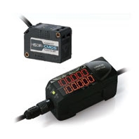
Stable measurement that is unaffected by workpiece changes. The simple setting for everyone.
Related Contents
- Displacement / Measurement Sensors
- Features
- Lineup
- Specifications
- Dimensions
- Catalog
last update: April 16, 2018
Tolerance class IT16 applies to dimensions in thes data sheet unless otherwise specified.
Units
Sensor Heads
ZX2-LD50
ZX2-LD50L
ZX2-LD100
ZX2-LD100L
ZX2-LD50V
* In the case of ZX2-LD50 (L), L=50, A=21 °
In the case of ZX2-LD100 (L), L=100, A=11.5 °
Note: Attach the enclosed ferrite core (16.5 dia., length: 30 mm) to the cable within 100 mm from the Sensor Head.
Amplifier Units
ZX2-LDA11
ZX2-LDA41
*1. Maximum height when cover open: 56
*2. Minimum length when connected: 50
Accessories (sold separately)
Calculating Unit
ZX2-CAL
Sensor Head Extension Cables
ZX2-XC1R
ZX2-XC4R
ZX2-XC9R
ZX2-XC20R
* Length L is as follows.
ZX2-XC1R: 1 m, ZX2-XC4R: 4 m, ZX2-XC9R: 9 m, ZX2-XC20R: 20 m
Minimum bending radius: 30 mm
Note: Attach the enclosed ferrite cores (16.5 dia., length: 30 mm) within 100 mm of each end of the extension cable.
ZX2-series Communications Interface Unit
ZX2-SF11
Mounting Bracket
E39-L178
Material: Stainless steel (SUS304)
Thickness: 3.0 mm
Accessories: Phillips screws (M3×30): 2, Nut plate: 1
Mounting Bracket
E39-L179
Material: Stainless steel (SUS304)
Thickness: 3.0 mm
Accessories: Phillips screws (M3×30): 2, Nut plate: 1
*Use this Mounting Bracket when installing the ZX2-LD100 (L) as a normal Diffuse-reflective or Regular-reflective Sensor Head.
Installation Method for Regular-reflective Sensor Head
Using a E39-L178 Mounting Bracket:
Note: When securing the Sensor Head in the Mounting Bracket, insert the screws into the side of the Sensor Head where
the warning label is located and secure the Sensor Head into place.
the warning label is located and secure the Sensor Head into place.
*1. The measurement distance reference position is the end of the Mounting Bracket.
*2. For the Regulalr-reflective Sensor Heads, rotate the Sensor Head counterclockwise, secure it in place, and then
perform any necessary fine adjustments.
perform any necessary fine adjustments.
Installation Method for Regular-reflective Sensor Heads
(Installing a Diffuse-reflective Sensor Head as a Regular-reflective Sensor Head)
Using a E39-L179 Mounting Bracket:
Note: When securing the Sensor Head in the Mounting Bracket, insert the screws into the side of the Sensor Head where
the warning label is located and secure the Sensor Head into place.
*1. The measurement distance reference position is the end of the Mounting Bracket.
*2. For the IInstalling a Diffuse-reflective Sensor as a Regular-reflective Sensor, rotate the Sensor Head
counterclockwise, secure it in place, and then perform any necessary fine adjustments.
counterclockwise, secure it in place, and then perform any necessary fine adjustments.
Not Using a Mounting Bracket:
Tilt the Sensor Head towards the workpiece as shown below.
Adjust the installation so that the angle is 10.5° ±0.1°.
* The mounting hole dimensions in parentheses (reference values) are for when the Sensor is installed at 10.5°.
Installation Method for Diffuse-reflective Sensor Heads
Using a E39-L178, E39-L179 Mounting Bracket:
*1 The measurement distance reference position is the Sensor’s sensing surface.
Note: When securing the Sensor Head in the Mounting Bracket, insert the screws into the side of the Sensor Head
where the warning label is located and secure the Sensor Head into place.
Not Using a Mounting Bracket:
Mount the Sensor Head in relation to the workpiece as shown below.
* ZX2-LD50 (L): 50
ZX2-LD100 (L): 100
last update: April 16, 2018
© Copyright OMRON Corporation 2007 - 2026. All Rights Reserved.