Page top

E2CY-SD

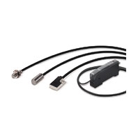
Non-ferrous-metal-detecting Proximity Sensor (Separate Amplifier Type)

E2CY-SD

Achieve stable detection of non-ferrous metals such as aluminum, copper, and stainless steel.

Sensors

Model E2CY-X1R5A
E2CY-C1R5A-1
E2CY-C2A(F) E2CY-V3A
Stable sensing distance 0 to 1.5 mm 0 to 2 mm 0 to 3 mm
Differential travel 10% max. of sensing distance with Amplifier Unit in FINE mode
15% max. of sensing distance with Amplifier Unit in NORM mode
Detectable object Non-ferrous metal
Standard sensing object Aluminum: 8 × 8 × 1 mm Aluminum: 12 × 12 × 1 mm
Response frequency *1 40 Hz min. with Amplifier Unit in FINE mode
100 Hz min. with Amplifier Unit in NORM mode
Ambient temperature range Operation: -10 to 55°C, Storage: -25 to 70°C (with no icing or condensation)
Ambient humidity range Operating and storage: 35% to 95% (with no condensation)
Temperature
influence *2
-10 to 55°C ±15% max. of sensing
distance at 23°C
distance at 23°C ±10%
max. of sensing distance at
23°C
±15% max. of sensing
distance at 23°C
0 to 40°C ±10% max. of sensing
distance at 23°C *3
±10% max. of sensing
distance at 23°C
Vibration resistance Destruction: 10 to 500 Hz, 2-mm double amplitude or 150 m/s2 for 2 hours each in X,
Y, and Z directions
Shock resistance Destruction: 500 m/s2 3 times each in X, Y, and Z directions
Degree of protection IEC 60529 IP67
Connection method Pre-wired (High-frequency coaxial cable, Standard cable length: 3 m)
Cable length compensation 0.5 to 5 m *4
Weight (packed state) Approx. 35 g
Materials Case Stainless steel Zinc die-cast
Sensing
surface
Heat-resistant ABS (E2CY-C2AF: Fluororesin)
Cable Soft PVC (E2CY-C2AF: Fluororesin)
Clamping nuts Nickel-plated brass (E2CY-X1R5A only)
Toothed
washers
Zinc-plated iron (E2CY-X1R5A only)
Mounting
screws
Zinc-plated iron (E2CY-V3A only)

*1. The average value when using the DC-switching control output on the Amplifier Unit.
       Measurement conditions are as follows: standard sensing object, a distance of twice the standard sensing object,
       and a set distance of half the stable sensing distance.
*2. When the temperature around the Amplifier Unit is stable at 23°C.
*3. E2CY-C1R5A-1: ±15% max. of sensing distance at 23°C
*4. When extending the cable, use a 1.5D-2V (equivalent to JIS C 3501) cable with characteristic impedance of 50 Ω.

Amplifier Unit

Model E2CY-SD11 E2CY-SD41
Power supply voltage 12 to 24 VDC ±10%, ripple: 10% max.
Power consumption 1,080 mW max. (45 mA max. at 24 VDC)
Sensing distance adjustment
range
10% max. of stable sensing distance
Sensitivity setting Teaching/manual adjustment
Control output NPN open collector (26.4 VDC max.),
load current:100 mA max.,
residual voltage: 1 V max.
PNP open collector (26.4 VDC max.),
load current: 100 mA max.,
residual voltage: 1 V max.
Functions OFF-delay timer 0 to 40 ms (1 to 20 ms: 1-ms increments, 20 to 40 ms: 5-ms increments)
Zero reset Supported.
Intial reset Supported. (All settings are returned to their default values.)
Hysteresis setting 3 to variable
Self diagnosis Displays errors (sensor disconnection, sensor short-circuit, or output short-circuit)
Operation mode Changed with NO/NC Switch.
Protection circuits Power supply reverse polarity protection and output short-circuit protection
Indicator Operation indicator (orange)
Digital display Detection amount display (FINE: 4,000 max., NORM: 2,000 max.), bar display, function
display (red)
Reverse display Supported.
Ambient temperature range Operation: -10 to 55°C, Storage: -25 to 70°C (with no icing or condensation)
Ambient humidity range Operating and storage: 35% to 85% (with no condensation)
Temperature influence * ±10% max. of sensing distance at 23°C in the temperature range of -10 to 55°C
Voltage influence ±1% max. of sensing distance in the rated voltage range ±10%
Insulation resistance 20 MΩ min. (at 500 VDC) between currentcarrying parts and case
Dielectric strength 1,000 VAC, 50/60 Hz for 1 minute. Between current-carrying parts and case
Vibration resistance Destruction: 10 to 150 Hz, 1.5-mm double amplitude or 100 m/s2 for 2 hours each
in X, Y, and Z directions
Shock resistance Destruction: 300 m/s2 3 times each in X, Y, and Z directions
Degree of protection IEC 60529 IP50 (with Sensor cable connected and protective cover attached)
Connection method Pre-wired (Standard cable length: 2 m)
Weight (packed state) Approx. 100 g
Materials Case PBT
Cover Polycarbonate
Cable connecting
screws
Zinc-plated iron
Accessories E39-L143 Mounting Bracket (SUS304 stainless steel), instruction manual

*1. If the Sensor approaches iron or other ferrous metals, the digital display will show negative values.
   There are exceptions. Refer to Fast Moving Ferrous Metals in Safety Precautions on Catalog.
*2. When the temperature around the Sensor is stable at 23°C.
Note: You can mount the Amplifier Unit on a DIN Track without using the Mounting Bracket.