| Certification body | Standards |
|---|---|
| TÜV Rheinland | • EN ISO 13849-1
• IEC 61508 parts 1-7 • IEC/EN 61131-2 |
| UL | • NRAG (UL 61010-1, UL 61010-2-201 and UL 121201)
• NRAG7 (CSA C22.2 No. 61010-1, CSA C22.2 No. 61010-2-201 and CSA C22.2 No. 213) |
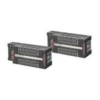
Safety I/O Terminal GI-S series
Related Contents
last update: June 3, 2024
| Certification body | Standards |
|---|---|
| TÜV Rheinland | • EN ISO 13849-1
• IEC 61508 parts 1-7 • IEC/EN 61131-2 |
| UL | • NRAG (UL 61010-1, UL 61010-2-201 and UL 121201)
• NRAG7 (CSA C22.2 No. 61010-1, CSA C22.2 No. 61010-2-201 and CSA C22.2 No. 213) |
By using GI-S-series safety I/O terminals, you can build a safety control system that meets the followings.
• Requirements for SIL 3 in IEC 61508
• Requirements for PLe/category 4 in EN ISO13849-1
Also, GI-S-series safety I/O terminals have been registered for conformity to RCM and KC (Korean radio regulation).
| Item | Specification | |
|---|---|---|
| Enclosure | Mounted in a panel (open type) | |
| Operating
environment |
Ambient operating temperature | 0 to 55°C |
| Ambient operating humidity | 10% to 95% (with no condensation or icing) | |
| Atmosphere | Must be free from corrosive gases | |
| Ambient storage temperature | -25 to 70°C (with no condensation or icing) | |
| Altitude | 2,000 m max. | |
| Pollution degree | 2 | |
| Insulation class | CLASS III (SELV) | |
| Overvoltage category | II | |
| EMC immunity level | Zone B: IEC 61131-2 | |
| Vibration resistance | Conforms to IEC 60068-2-6
5 to 8.4 Hz with amplitude of 3.5 mm 8.4 to 150 Hz, acceleration of 9.8 m/s2 100 min. in each X, Y, and Z directions (10 sweeps of 10 min. each = 100 min. total) |
|
| Shock resistance | Conforms to IEC 60068-2-27
147 m/s2 3 times in each X, Y, and Z directions |
|
| Insulation resistance | 20 MΩ between isolated circuits (at 100 VDC) | |
| Dielectric strength | 500 VAC between isolated circuits for 1 minute at a leakage current of
10 mA max. |
|
| Installation method | DIN Track mounting (IEC 60715 TH35-7.5/TH35-15) | |
| Degree of protection | IP20 | |
| Model | GI-SMD1624 | GI-SID1224 | |
|---|---|---|---|
| Number of safety input points | 12 | ||
| Number of safety output points | 4 | --- | |
| Number of test output points | 12 | ||
| OMRON special safety input device *1 | Connection unavailable | ||
| LED indication | [V0] LED, [IN[]] LED x 12, [V1] LED,
[OUT[]] LED x 4, [MS] LED, [NS] LED, [PORT[] LINK] LED x 2 |
[V0] LED, [IN[]] LED x 12,
[V1] LED, [MS] LED, [NS] LED, [PORT[] LINK] LED x 2 |
|
| Hardware switch setting | [IP ADDRESS] switch x3 (MODE, x16, x1)

* Factory default GI-SMD1624: 192.168.250.2 [IP ADDRESS] Switch= “002” GI-SID1224: 192.168.250.3 [IP ADDRESS] Switch= “003” |
||
| Safety input type | IEC61131-2 type3 PNP (sinking inputs) | ||
| Safety input current | 6 mA max. | ||
| Safety input ON voltage | 11 VDC min. | ||
| Safety input OFF voltage/OFF current | 5 VDC max./1 mA max. | ||
| Safety output type | Source output (for PNP) | ||
| Safety output rated current | 0.5 A max. | *2 | |
| Maximum total safety output current | 2.0 A | ||
| Safety output ON residual voltage | 1.2 V max.
(between V1 and each output terminal) |
||
| Safety output OFF residual voltage | 2.0 V max.
(between G1 and each output terminal) |
||
| Safety output leakage current | 0.1 mA max. | ||
| Test output type | Source output (for PNP) | ||
| Test output rated current | 0.7 A max. | ||
| Maximum total test output current | 5.0 A | ||
| Test output ON residual voltage | 1.2 V max. (between V0 and each output terminal) | ||
| Test output leakage current | 0.1 mA max. | ||
| External dimensions *3 | 170 (W) x 65 (H) x 55 (D) | ||
| Weight | 400 g | ||
| Number of communications that can be set
between NX Units |
254 ports max. *3 | ||
| Unit power
supplies |
Power supply voltage | 24 VDC (20.4 to 28.8 VDC) | |
| Current consumption *4 | 250 A max. | ||
| Inrush current | On cold start at normal temperature
50 A max., 0.1 ms max. |
||
| Power supply terminal
current carrying capacity *5 |
5 A | ||
| Insulation type | No insulation: Between unit power supply terminal and internal circuit | ||
| Output
power supply |
Power supply voltage | 24 VDC (20.4 to 28.8 VDC) | *2 |
| Current consumption | 50 A max. | ||
| Inrush current | On cold start at normal temperature
50 A max., 0.1 ms max. |
||
| Power supply terminal
current carrying capacity *5 |
5 A | ||
| Insulation type | Photocoupler insulation | ||
| External
connection terminal |
Communication connector | EtherNet/IP communication RJ45 x 2 | |
| Screwless clamp terminal
block |
Top terminal block
Functional earthing Unit power supply Input/Test output Bottom terminal block Output power supply Output/Input/Test output |
Top terminal block
Functional earthing Unit power supply Input/Test output Bottom terminal block Input/Test output |
|
| Inter-
terminal connection diagram |
V0/G0
Unit power supply |
 |
|
| V1/G1
Output power supply |
 |
*2 | |
| Installation direction and restriction | No restriction | ||
| Protective function | Overvoltage protection, overcurrent protection | ||
| Item | Specifications | ||
|---|---|---|---|
| GI-SMD1624 / GI-SID1224 | |||
| Communications protocol | TCP/IP, UDP/IP | ||
| Support services | Sysmac Studio connection, tag data links, CIP message
communication, DHCP (client) |
||
| Number of logical ports | 1 | ||
| Physical layer | 100BASE-TX | ||
| Transmission
specifications |
Media access method | CSMA/CD | |
| Modulation | Baseband | ||
| Transmission path | Star, daisy chain, mixed (star and daisy chain), ring (DLR) | ||
| Transmission rate | 100M bit/s (100BASE-TX) | ||
| Transmission media | Twisted-pair cable (shielded: STP): category 5/5e or higher | ||
| Transmission distance | 100m max. (distance between hub and node) | ||
| Number of cascaded connections | 50 nodes or less recommended | ||
| CIP messaging service:
Explicit message UCMM (non-connection type) |
Maximum number of clients that can communicate simultaneously:
8/Logical ports |
||
| Safety process data
communications |
Exclusive
Owner (EO) |
Input | 1 |
| Output | 1 | ||
| Standard process data
communications |
Input Only | 1 (Point to Point) | |
| Listen Only | 7 (Multi-Cast) | ||
| EtherNet/IP conformance test | CT9 compliant | ||
| Ethernet interface | 100BASE-TX
Auto Negotiation Auto-MDI |
||
| DLR (Device Level Ring) | Ring Node (Beacon-based) | ||
The following table shows the possible combinations of versions of GI-SMD/SID Safety I/O Terminals, Safety CPU Units, Communication Control Unit, NX-series CPU Unit, and software. Refer to the GI-S-series Safety I/O Terminal User's Manual (Cat. No. Z400) for details.
| Safety I/O terminal | Supported Version | ||||||
|---|---|---|---|---|---|---|---|
| Model | Unit
version |
Safety
CPU Unit NX-SL5700 NX-SL5500 |
Communi-
cation Control Unit NX-CSG320 |
Machine
Automation Controller NX102-[][][][] |
Sysmac
Studio |
Network
Configurator |
Network
Configurator for DeviceNe Safety |
| GI-SMD1624 | Ver. 1.0 | Ver. 1.3 | Ver. 1.01 | Ver. 1.31 | Ver.1.24 or
higher |
Ver.3.67 or
higher |
Ver.3.42 or
higher |
| GI-SID1224 | Ver. 1.0 | Ver. 1.3 | Ver. 1.01 | Ver. 1.31 | Ver.1.24 or
higher |
Ver.3.67 or
higher |
Ver.3.42 or
higher |
last update: June 3, 2024
© Copyright OMRON Corporation 2007 - 2026. All Rights Reserved.