Question
What causes contact welding and what can be done about it?
Answer
Causes:
Overload that does not match the contact switching capacity
Inrush current larger than rating
Breaking current larger than rating
Switching frequency in excess of allowable operating frequency
Usage in a location subject to continuous vibration
Countermeasures:
Switch the load using a relay or a contactor.
A protective circuit is required so that loads such as relays, motors, incandescent bulbs, and solenoids can be used properly.
Cause:
Overload that does not match the contact switching capacity
Countermeasures:
Switch the load using a relay or a contactor.
Insert a contact protection circuit.
Typical Examples of Contact Protective Circuits (Surge Killers)
| Circuit example | Applicable current | Feature | Element selection | ||
| AC | DC | ||||
| CR circuit | 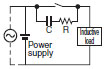 | * Conditional | Applicable | * When AC is switched, the load impedance must be lower than the C and R impedance. | C: 0.5 to 1 μF per switching current (1 A) R: 0.5 to 1 Ω per switching voltage (1 V) The values may change according to the characteristics of the load. The capacitor suppresses the spark discharge of current when the contacts are open. The resistor limits the inrush current when the contacts are closed again. Consider these roles of the capacitor and resistor and determine the ideal capacitance and resistance values from experimentation. Use a capacitor with a dielectric strength between 200 and 300 V. When AC is switched, make sure that the capacitor has no polarity. If, however, the ability to control arcs between contacts is a problem for high DC voltage, it may be more effective to connect a capacitor and resistor between the contacts across the load. Check the results by testing in the actual application. |
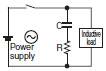 | Applicable | Applicable | The operating time will increase if the load is a relay or solenoid. It is effective to connect the CR circuit in parallel to the load when the power supply voltage is 24 or 48 V and in parallel to the contacts when the power supply voltage is 100 to 200 V. | ||
| Diode method | 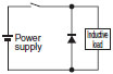 | Not applicable | Applicable | Energy stored in the coil is changed into current by the diode connected in parallel to the load. Then the current flowing to the coil is consumed and Joule heat is generated by the resistance of the inductive load. The reset time delay in this method is longer than that of the CR method. | The diode must withstand a peak inverse voltage 10 times higher than the circuit voltage and a forward current as high as or higher than the load current. |
| Diode and Zener diode method | 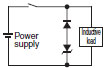 | Not applicable | Applicable | This method will be effective if the reset time delay caused by the diode method is too long. | Zener voltage for a Zener diode must be about 1.2 times higher than the power source since the load may not work under some circumstances. |
| Varistor method | 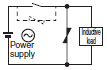 | Applicable | Applicable | This method makes use of constant-voltage characteristic of the varistor so that no high-voltage is imposed on the contacts. This method causes a reset time delay more or less. It is effective to connect varistor in parallel to the load when the supply voltage is 24 to 48 V and in parallel to the contacts when the supply voltage is 100 to 200 V. | Select the varistor so that the following condition is met for the cut voltage Vc. For AC currents, the value must be multiplied by √2. Vc > (Current Voltage × 1.5) If Vc is set too high, however, the voltage cut for high voltages will no longer be effective, diminishing the effect. |
Do not apply contact protective circuit as shown below.
 | This circuit effectively suppresses arcs when the contacts are OFF. The capacitance will be charged, however, when the contacts are OFF. Consequently, when the contacts are ON again, short-circuited current from the capacitance may cause contact weld. |
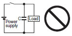 | This circuit effectively suppresses arcs when the contacts are OFF. When the contacts are ON again, however, charge current flows to the capacitor, which may result in contact weld. |


