Level Switches
These devices equip electrodes to detect liquid levels. They have been widely used in water works and sewers for buildings and housing complexes, industrial facilities and equipment, water treatment plants and sewage treatment facilities, and many other applications.
| Introduction | Features |
|
|
|
| Engineering Data |
|
|
|
|
What Is a Level Controller?
A Conductive Level Controller electrically detects the level of a liquid. Conductive Level Controllers (61F) are electronic liquid level detectors used in a wide range of applications such as water and sewer services for office and apartment buildings, industrial applications for iron and steel, food, chemical, pharmaceutical, and semiconductor industries, and liquid level control for agricultural water, water treatment plants, and wastewater plants. When the electrodes are in contact with liquid, the circuit is closed (the liquid completes the path for electricity to flow) and the electrical current that flows in this circuit is used to detect the level of the liquid. A variety of conductive liquids can be controlled using this method. Detecting the resistance between the electrodes and comparing it to see if it is larger or smaller than a reference resistance is used to detect the surface of the liquid.
Principles
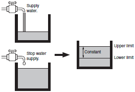
The operating principle is explained using a case where water is supplied from the water mains.
Office and apartment buildings normally have a ground tank and an elevated tank. Water is supplied from the water mains into the ground tank, pumped up to the elevated tank, then distributed to each floor.
When the water level in the elevated tank is low, water is pumped up from the ground tank to supplement it. When the water level reaches a certain level, the pump stops. (See figure 1.)
Elevated tanks are controlled in this manner to maintain the water level within upper and lower limits as shown below.
Figure 1. Water Supply Control
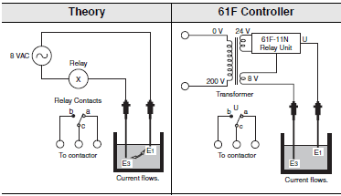
Pump Control According to Water Level (Two-pole Method)
(1)When electrode E1 is not in contact with the conductive liquid as shown in figure 2, the electrical circuit is open, and no current flows between electrodes E1 and E3.
Consequently relay X does not operate and the contact remains at the b side.
(2)When electrode E1 is in contact with the conductive liquid as shown in figure 3, the circuit closes due to the conductive fluid completing the circuit between E1 and E3.
Relay X operates and switches to the a side.
By connecting the relay contacts to a contactor, the pump can be turned ON and OFF.
However in practice, with only two electrodes, ripples on the surface of the liquid cause the relay to switch rapidly.
This problem can be solved by forming a self-holding circuit. (The configuration shown in figures 2 and 3 can be used as water level alarms.)
Figure 2. Low Water Level
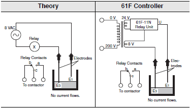
Figure 3. High Water Level
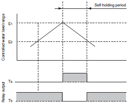
Liquid Level Control with Self-Holding Circuit (Three-pole Method)
An extra electrode E2 is added, and E1 and E2 are connected via contact a2 as shown in figure 4. When electrode E1 is in contact with the conductive liquid (as in point 2 of previous section), relay X operates and switches to the a side. Even if the liquid level falls below E1, the electrical circuit made through the liquid and the electrodes is retained by E2 and E3, as long as contact a2 is closed.
This kind of circuit made from electrode E2 and a contact is called a self-holding circuit.
When the liquid level falls below E2, the circuit made through the electrode circuit opens, which de-energizes relay X, thus closing the NC contact of X. This enables control of relay X to be switched ON and OFF between E1 and E2.
Figure 5 shows the timing chart of this mechanism.
Operating as simply as it does, possible applications of the Conductive Level Controller other than liquid level control include applications as leakage detection, and object size discrimination.
Figure 4. Self-holding Circuit
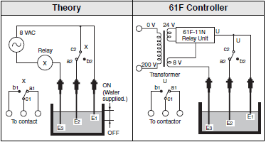
Figure 5. Timing Chart
Note:Non-conductive liquids, such as oil, cannot be controlled using this method.
Configuration Example
Conductive Level Controllers are basically composed of three components: a Level Controller, Electrode Holder, and Electrodes.
When you select a product, select each of these components for your application.
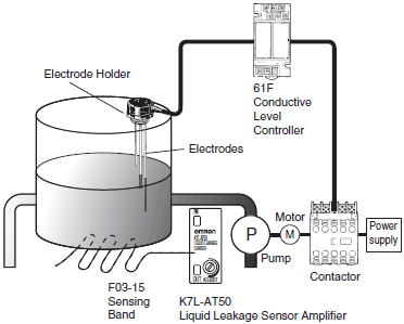
Liquid level control is performed by combining the 61F Level Controller, Electrode Holder, and Electrodes.
61F Level Controller
Select the Level Controller according to the control method, mounting method, liquid to detect, and length of wiring.
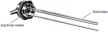
Electrode Holder
Select the Electrode Holder according to the environment in the water tank and the installation environment of the water tank.
Electrodes
Select the Electrodes according to the environment in the water tank and the control range.
Note:The 61F Level Controller, Electrode Holder, and Electrodes are sold separately.