Axial Fans
OMRON's complete lineup includes water-resistant AC Axial Fans with superior resistibility to water and dirt, and General-purpose AC Axial Fans.
|
|
Features |
| Principles | Classifications |
| Engineering Data | Further Information |
|
|
Troubleshooting |
Flow Rate and Static Pressure
The characteristic graphs provided for each of the models represent the average of actual measurement data obtained under the measurement conditions given below. They are provided as reference for determining the Fan most suitable
for the type of cooling required; the actual characteristics may differ from the values represented in the graphs. The graphs are not intended to guarantee these characteristic values.
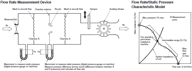
A simple explanation of the flow rate/static pressure characteristics and the methods of measuring them is given below.


Fully close the damper. Take the pressure difference between chamber B and ambient pressure (Ps). The maximum value of the pressure difference (Ps) is the maximum static pressure (Ps max).

Adjust the auxiliary blower to change the static pressure (Ps).
Measure the pressure difference between chamber A and chamber B (Pd). Calculate the flow rate (Q).

Fully open the damper and adjust the auxiliary blower to set the static pressure to zero (0). Measure the pressure difference between chamber A and chamber B (Pd). Take the flow rate (Q) calculated at this point as the maximum flow rate (Q max.).
Measurement Conditions
| Number of Fans tested | Ambient conditions | Measurement device |
| 5 | Temperature: 23 ±2°C Humidity: 65% ±5% | Measurement was performed using the multi-nozzle double chamber method based on AMCA (Air Moving Condition Association, U.S.A.) Standards 270 to 274. |
Fan Operating Point:
A Fan installed in equipment operates near the point where the Fan characteristic curve crosses the system impedance curve.
Note: The maximum flow rate and maximum static pressure do not indicate the Fan operating point when it is installed in equipment. However, these characteristics are important for comparing Fan performances and for selecting Fans.
Serial and Parallel Fan Operation
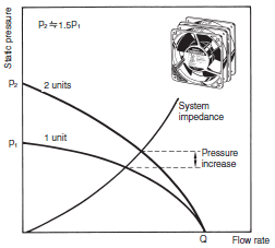
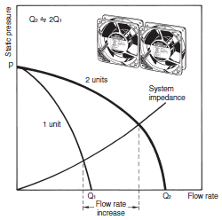
The characteristics of two identical Fans operated in series or parallel are determined as shown in the following diagrams.
Serial Operation:
Parallel Operation:
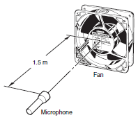
Noise Measurements
Measurements are performed according to JIS B 8346 (Noise Level Measurement Method for Blowers and Compressors).
R87F: Measurement is performed at a position 1.5 m above the center line from the air inlet.
R89F: Measurement is performed at a position 1 m away from the air inlet.
Measurement with R87F
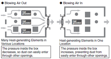
Cooling Effect
Use the location and number of heat-generating elements to determine which is more efficient, blowing air out or blowing air in.
Service Life
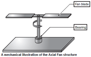
The service life of an Axial Fan is generally determined by the bearings.
The following diagram is a simple, mechanical illustration of the Fan structure.
The Fan blade will turn smoothly if the bearings are in normal condition. When there is an abnormality in the bearings, however, the friction between the shaft and the bearings will increase until the blade eventually stops turning.
This is the definition of a Fan's service life.
