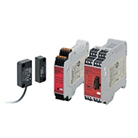
Page top

Lead Contents

Compact Non-Contact Door Switch/Flexible Safety Unit

D40A/G9SX-NS

D40A/G9SX-NS

Electronic Detection Mechanism for Better Stability in Non-contact Door Switch Operation

Primary Contents


Ratings and Characteristics (Non-contact Door Switches)

ModelD40A-1C[]
Operating
characteristics *1
Operating distance
OFF→ ON
5 mm min.
Operating distance
ON→ OFF
15 mm max.
Differential travelRefer to Datasheet.
Influence of
temperature (max.)
±20% of operating distance at 23°C, within temperature range of -10 to 55°C
Ambient operating temperature-10 to 55°C (no icing or condensation)
Ambient operating humidity25% to 85%
Insulation resistance
(between charged parts and case)
50 MΩ max. (at 500 VDC)
Dielectric strength
(between charged parts and case)
1,000 VAC for 1 min
Vibration resistance10 to 55 to 10 Hz (single amplitude: 0.75 mm, double amplitude: 1.5 mm)
Shock resistance300 m/s2 min.
Degree of protectionIP67
MaterialPBT resin
Mounting methodM4 screws
Terminal screw tightening torque1 Nm
Power consumption0.6 W max.
Auxiliary outputs *224 VDC, 10 mA (PNP open-collector outputs)
LED indicatorsActuator not detected (red); actuator detected (yellow)
Connection cables2 m, 5 m
Number of connectable switches *330 max. (wiring length: 100 m max.)
WeightSwitch: approx. 145 g, actuator: approx. 20 g (D40A-1C2)

*1.This is the distance where the switch operates from OFF to ON when approaching and the distance where the switch operates from ON to OFF when separating when the switch and actuator target marks are on the same axis, and the sensing surfaces coincide.
*2.Turns ON when the actuator is approaching.
*3.For details, refer to Precautions for Correct Use on Datasheet.

Ratings (Non-contact Door Switch Controllers)

Power input

ModelG9SX-NS202-[]G9SX-NSA222-T03-[]G9SX-EX-[]
Rated supply voltage24 V DC
Operating voltage range-15% to 10% of rated supply voltage
Rated power consumption *3 W max.4 W max.2 W max.

*Power consumption of loads not included.

Inputs

ModelG9SX-NS202-[]/G9SX-NSA222-T03-[]
Safety input *Operating voltage: 20.4 VDC to 26.4 VDC, internal impedance: approx. 2.8 kΩ
Feedback/reset input

*Only applies to the G9SX-NSA222-T03-[]. Refers to input other than that from the Non-contact Door Switch.

Outputs

ModelG9SX-NS202-[]/G9SX-NSA222-T03-[]
Instantaneous safety output *1
OFF-delayed safety output *1
P channel MOS FET transistor output
Load current: 0.8 A DC max. *2
Auxiliary outputPNP transistor output
Load current: 100 mA max.

*1.While safety outputs are in the ON state, the following signal sequence is output continuously for diagnosis.
When using the safety outputs as input signals to control devices (i.e. Programmable Controllers), consider the OFF pulse shown below.

D40A/G9SX-NS_Spec1

*2.The following derating is required when Units are mounted side-by-side.
G9SX-NS202-[]/G9SX-NSA222-T03-[]: 0.4 A max. load current

Expansion Unit

ModelG9SX-EX-[]
Rated load250 VAC, 3 A/30 VDC, 3 A (resistive load)
Rated carry current3 A
Maximum switching voltage250 VAC, 125 VDC

Characteristics

ModelG9SX-NS202-[]G9SX-NSA222-T03-[]G9SX-EX-[]
Over-voltage category
(IEC/EN 60664-1)
IIII (Relay outputs 13 to 43 and 14 to 44: III)
Operating time (OFF to ON state) *1100 ms max.
(Logical AND connection input ON and Non-contact Door Switch input ON)
50 ms max.
(Safety input: ON) *2
100 ms max.
(Logical AND connection input ON and Non-contact Door Switch input ON) *3
30 ms max. *4
Response time (ON to OFF state) *115 ms max.
(Logical AND connection input: OFF)
20 ms max.
(Non-contact Door Switch input OFF) *6
15 ms max.
(Safety input OFF and logical AND connection input OFF)
20 ms max.
(Non-contact Door Switch input: OFF) *6
10 ms max. *4
ON-state residual voltage3.0 V max. (safety output, auxiliary output)
OFF-state leakage current0.1 mA max. (safety output, auxiliary output)
Maximum wiring length of safety
input, logical AND connection
input, and Non-contact Door
Switch input
100 m max.
(External connection impedance: 100 Ω max. and 10 nF max.)
Reset input time
(Reset button pressing time)
100 ms min.
Accuracy of OFF-delay time *5---Within ±5% of the set valueWithin ±5% of the set value
Insulation
resistance
Between logical AND
connection terminals,
and power supply input
terminals and other
input and output
terminals connected
together
20 MΩ min. (at 100 VDC)---
Between all terminals
connected together
and DIN rail
100 MΩ min.
(at 500 VDC)
Dielectric
strength
Between logical AND
connection terminals,
and power supply input
terminals and other
input and output
terminals connected
together
500 VAC for 1 min.---
Between all terminals
connected together
and DIN rail
1,200 VAC for 1 min
Between different poles of outputs---
Between relay outputs connected together and other terminals connected together2,200 VAC for 1 min
Vibration resistance10 to 55 to 10 Hz, 0.375 mm single amplitude
(0.75 mm double amplitude)
Shock
resistance
Destruction300 m/s2
Malfunction100 m/s2
DurabilityElectrical---100,000 cycles min.
(rated load, switching frequency: 1,800 cycles/hour)
Mechanical---5,000,000 cycles min.
(switching frequency: 7,200 cycles/hour)
Ambient operating temperature-10 to 55°C (no icing or condensation)
Ambient operating humidity25% to 85%
Terminal tightening torque0.5 Nm (For the G9SX-NS[]-RT (with screw terminals) only)
WeightApprox. 125 gApprox. 200 gApprox. 165 g

*1.When two or more Units are connected by logical AND, the operating time and response time are the sum total of the operating times and response times, respectively, of all the Units connected by logical AND.
*2.Represents the operating time when the safety input turns ON with all other conditions set.
*3.Represents the operating time when the logical AND input and the Non-contact Door Switch input turn ON with all other conditions set.
*4.This does not include the operating time or response time of G9SX-NS[] that are connected.
*5.This does not include the operating time or response time of internal relays in the G9SX-EX-[].
*6.The failure detection time for 24 V short-circuit failure on the input to Non-contact Door Switches is 35 ms max.
If using the Switch for an application other than as a Door Switch, calculate the safe distance using a failure detection time of 35 ms.

Logical AND Connection

ModelG9SX-NS202-[]G9SX-NSA222-T03-[]G9SX-EX-[]
Number of Units connected
per logical AND output
4 Units max.---
Total number of Units
connected by logical AND *1
20 Units max.---
Number of Units connected
in series by logical AND
5 Units max.---
Max. number of Expansion
Units connected *2
---5 Units max.
Maximum cable length for
logical AND input
100 m max.---

Note: See Logical AND Connection Combinations below for details.
*1.The number of G9SX-EX401-[] Expansion Units or G9SX-EX041-T-[] Expansion Units (OFF-delayed Model) not included.
*2.G9SX-EX401-[] Expansion Units and G9SX-EX041-T-[] Expansion Units (OFF-delayed Model) can be mixed.

Caution: In the interenst of product improvement, specifications are subject to change without notice.