Page top

Primary Contents


Ratings

ItemK3GN-ND
With DC voltage, DC current, and NPN input
K3GN-PD
With DC voltage, DC current, and PNP input
Supply voltage24 VDC
Operating voltage range85% to 110% of the rated supply voltage
Power consumption
(at max. load)
(See note 1.)
2.5 W max. (at max. DC load with all indicators lit)
Input signalDC voltage, DC current, no-voltage contact, open collector
DC voltage/
current input
A/D conversionDouble integral method
Pulse signal
input
Pulse measurement
method
Periodic measurement method
External power
supply
None
Control inputPresent value hold or forced zero (selectable) (See note 2.)
Outputs
(Outputs depend on
the model.)
Relay contact output1 A, 30 VDC (resistive load), mechanical life: 50,000,000 operations min., electrical life: 100,000 operations min.
Transistor outputMax. load voltage: 24 VDC, Max. load current: 50 mA, Leakage current: 100 μ A max.
Communications
output
RS-485 (2-wire, half-duplex)
Linear outputDC current
(0 to 20 mA DC, 4 to 20 mA: Load: 500 Ω max.,
Resolution: Approx. 10,000)
DC voltage
(0 to 5 VDC, 1 to 5 VDC, 0 to 10 VDC: Load: 5k Ω min.,
Resolution: Approx. 10,000)
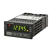
---
DisplayNegative LCD (backlit LCD) display
7-segment digital display, character height: 7.0 mm, and single illuminated display
Main functionsScaling, prescaling, teaching, average processing, forced zero, display color selection, output type selection, key protection, startup compensation timer, hysteresis
Ambient temperatureOperating: -10°C to 55°C (with no condensation or icing)
Storage: -25°C to 65°C (with no condensation or icing)
Ambient humidityOperating: 25% to 85%
Altitude2,000 m max.
AccessoriesRubber packing, fixture, operation manual

Note:

1. A control power supply capacity greater than the rated capacity is required when the Digital Panel Meter is turned ON. Do not forget to take this into consideration when using several Digital Panel Meters. When power is supplied, all indicators will light and outputs will be OFF. When using startup compensation time operation, the display will read "00000" and all outputs will be OFF.

2. Enabled only when using DC voltage/current input. (Min.time for control signal input: 80 ms)

Characteristics

ItemK3GN-ND
With DC voltage, DC current, and NPN input
K3GN-PD
With DC voltage, DC current, and PNP input
Input signalDC voltage/current (4 to 20 mA, 1 to 5 V, ±5 V, ±10 V)
No-voltage contact (30 Hz max. with ON/OFF pulse width of 16 ms min.)
Open collector (5 kHz max. with ON/OFF pulse width of 90 μs min.)
Displayable range5 digits (-19999 to 99999)
Sampling period250 ms
Display refresh
period
Sampling period (sampling times multiplied by number of averaging times if average processing is selected.)
Comparative output
response time
(transistor outputs)
750 ms max. (transistor output)
(The time required for the judgment output to be output if the input signal rapidly changes from 15% to 95% or from 95% to 15%.)
Linear output
response time
750 ms max. (The time required for the
analog output to be output if the output
signal rapidly changes from 15% to 95% or
from 95% to 15%.)
---
Insulation
resistance
20 MΩ min. (at 500 VDC) between external terminal and case.
Insulation provided between inputs, outputs, and power supply.
Dielectric
strength
1,000 VAC for 1 min between external terminal and case.
Noise immunity±480 V on power supply terminals in normal mode, ±1,500 V in common mode, ±1 μs, or 100 ns for square-wave noise with 1 ns
Vibration
resistance
Vibration frequency: 10 to 55 Hz, Acceleration: 50 m/s2 for 10 min each in X, Y, and Z directions
Shock
resistance
Models with transistor outputs: 150 m/s2 three times each in 3 axes, 6 directions
Models with contact outputs: 100 m/s2 three times each in 3 axes, 6 directions
WeightApprox. 100 g (Main Unit only)
Degree of
protection
Front panelNEMA4X for indoor use (equivalent to IP66),
IP20
IP00 and finger protection (VDE0106/100)
Rear case
Terminals
Memory
protection
Non-volatile memory (EEPROM) (possible to rewrite 100,000 times)
Approved
standards
UL508, CSA C22.2 No. 142
EMC(EMI) EN 61326 Industry
Emission Enclosure: EN55011 Group 1 class A

(EMS) EN 61326 Industry
Immunity ESD: EN 61000-4-2: 4 kV (contact discharge)
8 kV (air discharge)
Immunity RF-interference: EN 61000-4-3: 10 V/m (amplitude-modulated, 80 MHz to 1 GHz)
Immunity Fast Transient Noise: EN 61000-4-4: 2 kV (power line)
Immunity Burst Noise: 1 kV line to line (I/O signal line)
Immunity Surge: EN 61000-4-5: 2 kV line to ground (power line)
Immunity Conducted Disturbance EN 61000-4-6: 3 V (0.15 to 80 MHz)
Immunity Power Frequency Magnetic EN 61000-4-8: 30 A/m (50 Hz) continuous time

Input Ranges: Measurement Range and Accuracy

Input type
Analog
Pulse
Remote
DC current inputDC voltage inputRotary pulse
Analog range
4 to 20 mA
Analog range
1 to 5 V
±5 V
±10 V
Pulse frequency
30 Hz
5 kHz
Connection terminal(5)-(6)Connection terminal(4)-(5)Connection terminal(2)-(3)
Input impedance60 ΩInput impedance1 M Ω min.------
Measurement accuracy±0.1% full scale ± one digit max. (at 23±3°C)±0.1% full scale ± one digit max. (at 23±5°C)±0.1% full scale ± one digit max. (at 23±5°C)---

Note: The shaded ranges indicate default settings.

Input/Output Ratings

Relay Contact Output

(Incorporating G6K Relays)

ItemResistive load (cosΦ = 1)
Rated load1 A at 30 VDC
Rated through current1 A max. (at COM terminal)
Max. contact voltage60 VDC
Max. contact current1 A (at COM terminal)
Max. switching capacity30 VA
Min. permissible load
(P level, reference value)
10 mV, 10 μA
Mechanical life50,000,000 operations min. (at a switching frequency of 36,000 operations/hr)
Electrical life
(at an ambient temperature of 23°C)
100,000 operations min. (at the rated load with a switching frequency of 1,800 operations/hr)

Transistor Output

Rated load voltage24 VDC
Max. load current50 mA
Leakage current100 μA max.

Communications Specifications

ItemRS-485
Communications method2-wire, half-duplex
Synchronization methodStart-stop synchronization
Baud rate1,200/2,400/4,800/9,600/19,200 bps
Transmission codeASCII
CommunicationsReading/Writing to the K3GNRead/write comparative set values, read/write scaling values, enable/disable the writing of data through communications, forced-zero control, and other data.

Linear Output

Item0 to 20 mA4 to 20 mA0 to 5 V1 to 5 V0 to 10 V
Permissible load impedance500 Ω max.5 kΩ min.
ResolutionApprox. 10,000
Output error±0.5% full scale±0.5 full scale.
±0.15 V at 1 V or less (no output for 0 or less)

Caution: In the interenst of product improvement, specifications are subject to change without notice.