Page top

E5EC, E5EC-B

Digital Temperature Controller (48 x 96 mm)

E5EC, E5EC-B

48 x 96 mm. Large White PV Display That's Easier to Read. Easy to Use, from Model Selection to Setup and Operation. A Complete Range of I/O Capacities, Functions, and Performance. Handles More Applications. E5EC-B is our Value Design product which increase the value of your control panel.

Software Download

You can download and install ThermoMini Software.

Ratings

Power supply voltage A in model number: 100 to 240 VAC, 50/60 Hz
D in model number: 24 VAC, 50/60 Hz; 24 VDC
Operating voltage range 85 to 110% of rated supply voltage
Power consumption Models with option selection of 000:6.6 VA max. at 100 to 240 VAC, and 4.1 VA max. at
24 VAC or 2.3 W max. at 24 VDC
All other models: 8.3 VA max. at 100 to 240 VAC, and 5.5 VA max. at 24 VAC or 3.2 W
max. at 24 VDC
Sensor input Temperature input
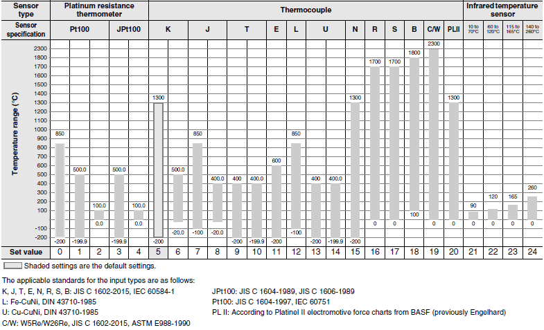
Thermocouple: K, J, T, E, L, U, N, R, S, B, C/W, or PL II
Platinum resistance thermometer: Pt100 or JPt100
Infrared temperature sensor (ES1B): 10 to 70°C, 60 to 120°C, 115 to 165°C, or 140 to
260°C
Analog input
Current input: 4 to 20 mA or 0 to 20 mA
Voltage input: 1 to 5 V, 0 to 5 V, or 0 to 10 V
Input impedance Current input: 150 Ω max., Voltage input: 1 MΩ min.
(Use a 1:1 connection when connecting the ES2-HB-N/THB-N.)
Control method ON/OFF or 2-PID control (with auto-tuning)
Control
output
Relay output SPST-NO, 250 VAC, 5 A (resistive load), electrical life: 100,000 operations,
minimum applicable load: 5 V, 10 mA (reference value)
Voltage output
(for driving SSR)
Output voltage: 12 VDC ± 20% (PNP), max. load current: 40 mA, with short-circuit
protection circuit (The maximum load current is 21 mA for models with two control
outputs.)
Linear current
output
4 to 20 mA DC/0 to 20 mA DC, load: 500 Ω max., resolution: approx. 10,000
Auxiliary
output
Number of outputs E5EC: 4
E5EC-B: 2 or 4 (depends on model)
Output
specifications
SPST-NO. relay outputs, 250 VAC, Models with 2 outputs: 3 A (resistive load),
Electrical life: 100,000 operations, Minimum applicable load: 10 mA at 5 V (reference
value)
Event
input
Number of inputs 2, 4 or 6 (depends on model)
External contact
input
specifications
Contact input: ON: 1 kΩ max., OFF: 100 kΩ min.
Non-contact input: ON: Residual voltage: 1.5 V max., OFF: Leakage current: 0.1 mA max.
Current flow: Approx. 7 mA per contact
Transfer
output
Number of outputs 1 (only on models with a transfer output)
Output
specifications
Current output: 4 to 20 mA DC, Load: 500 Ω max., Resolution: Approx. 10,000
Linear voltage output: 1 to 5 VDC, load: 1 kΩ min., Resolution: Approx. 10,000
Remote SP input Current input: 4 to 20 mA DC or 0 to 20 mA DC (input impedance: 150 Ω max.)
Voltage input: 1 to 5 V, 0 to 5 V, or 0 to 10 V (input impedance: 1 MΩ min.)
Potentiometer input * 100 Ω to 10 kΩ
Setting method Digital setting using front panel keys
Indication method 11-segment digital display and individual indicators
Character height: PV: 18.0 mm, SV: 11.0 mm, MV: 7.8 mm
Three displays Contents: PV/SV/MV, PV/SV/Multi-SP, or PV/SV/Remaining soak time, etc
Numbers of digits: 4 digits each for PM, SV, and MV displays
Multi SP Up to eight set points (SP0 to SP7) can be saved and selected using the event inputs,
key operations, or serial communications.
Bank switching None
Other functions Manual output, heating/cooling control, loop burnout alarm, SP ramp, other alarm
functions, heater burnout (HB) alarm (including SSR failure (HS) alarm), 40% AT, 100%
AT, MV limiter, input digital filter, self tuning, robust tuning, PV input shift, run/stop,
protection functions, extraction of square root, MV change rate limit, logic operations,
temperature status display, simple programming, moving average of input value, and
display brightness setting
Ambient operating
temperature
-10 to 55°C (with no condensation or icing), For 3-year warranty: -10 to 50°C with
standard mounting (with no condensation or icing)
Ambient operating humidity 25 to 85%
Storage temperature -25 to 65°C (with no condensation or icing)
Altitude 2,000 m max.
Recommended fuse T2A, 250 VAC, time-lag, low-breaking capacity
Installation environment Overvoltage category II, Pollution Degree 2 (EN/IEC/UL 61010-1)

* This function is not supported by the E5EC-B. Refer to Model Number Legend on Data Sheet.

Input Ranges

Thermocouple/Platinum Resistance Thermometer (Universal inputs)

E5EC, E5EC-B Specifications 4

Analog input

Input type Current Voltage
Input specification 4 to 20 mA 0 to 20 mA 1 to 5 V 0 to 5 V 0 to 10 V
Setting range Usable in the following ranges by scaling:
-1999 to 9999, -199.9 to 999.9,
-19.99 to 99.99 or -1.999 to 9.999
Set value 25 26 27 28 29

Alarm Types

Each alarm can be independently set to one of the following 19 alarm types. The default is 2: Upper limit. (see note.)
Auxiliary outputs are allocated for alarms. ON delays and OFF delays (0 to 999 s) can also be specified.
Note: In the default settings for models with HB or HS alarms, alarm 1 is set to a heater alarm (HA) and the Alarm Type 1
          parameter is not displayed.
          To use alarm 1, set the output assignment to alarm 1.

E5EC, E5EC-B Specifications 6

Characteristics

Indication accuracy
(at the ambient
temperature of 23°C)
Thermocouple: (±0.3% of indication value or ±1°C, whichever is greater) ±1 digit max. *1
Platinum resistance thermometer: (±0.2% of indication value or ±0.8°C, whichever is
greater) ±1 digit
Analog input: ±0.2% FS ±1 digit max.
CT input: ±5% FS ±1 digit max.
Potentiometer input: ±5% FS ±1 digit max.
Transfer output accuracy ± 0.3% FS max.
Remote SP Input Type ± 0.2% FS ± 1 digit max.
Influence of
temperature *2
Thermocouple input (R, S, B, C/W, PL II): (±1% of indication value or ±10°C, whichever is
greater) ±1 digit max.
Other thermocouple input: (±1% of indication value or ±4°C, whichever is greater) ±1 digit
max. *3
Platinum resistance thermometer: (±1% of indication value or ±2°C, whichever is greater) ±1
digit max.
Analog input: ±1%FS ±1 digit max.
CT input: ±5% FS ±1 digit max.
Remote SP input: ±1% FS ±1 digit max.
Influence of voltage *2
Influence of EMS.
(at EN 61326-1)
Input sampling period 50ms
Hysteresis Temperature input: 0.1 to 999.9°C or °F (in units of 0.1°C or°F)
Analog input: 0.01% to 99.99% FS (in units of 0.01% FS)
Proportional band (P) Temperature input: 0.1 to 999.9°C or °F (in units of 0.1°C or °F)
Analog input: 0.1 to 999.9% FS (in units of 0.1% FS)
Integral time (I) Standard, heating/cooling, or Position-proportional (Close): 0 to 9999 s (in units of 1 s), 0.0
to 999.9 s (in units of 0.1 s)
Position-proportional (Floating): 1 to 9999 s (in units of 1 s), 0.1 to 999.9 s (in units of 0.1 s)
*4
Derivative time (D) 0 to 9999 s (in units of 1 s), 0.0 to 999.9 s (in units of 0.1 s) *4
Proportional band (P)
for cooling
Temperature input: 0.1 to 999.9°C or °F (in units of 0.1°C or °F)
Analog input: 0.1 to 999.9% FS (in units of 0.1% FS)
Integral time (I) for
cooling
0 to 9999 s (in units of 1 s), 0.0 to 999.9 s (in units of 0.1 s) *4
Derivative time (D) for
cooling
0 to 9999 s (in units of 1 s), 0.0 to 999.9 s (in units of 0.1 s) *4
Control period 0.1, 0.2, 0.5, 1 to 99 s (in units of 1 s)
Manual reset value 0.0 to 100.0% (in units of 0.1%)
Alarm setting range -1999 to 9999 (decimal point position depends on input type)
Influence of signal
source resistance
Thermocouple: 0.1°C/Ω max. (100 Ω max.)
Platinum resistance thermometer: 0.1°C/Ω max. (10 Ω max.)
Insulation resistance 20 MΩ min. (at 500 VDC)
Dielectric strength 3,000 VAC, 50/60 Hz for 1 min between terminals of different charge
Vibration Malfunction 10 to 55 Hz, 20 m/s2 for 10 min each in X, Y, and Z directions
Resistance 10 to 55 Hz, 20 m/s2 for 2 hrs each in X, Y, and Z directions
Shock Malfunction 100 m/s2, 3 times each in X, Y, and Z directions
Resistance 300 m/s2, 3 times each in X, Y, and Z directions
Weight Controller: Approx. 210 g, Mounting Adapter: Approx. 4 g × 2
Degree of protection Front panel: IP66, Rear case: IP20, Terminals: IP00
Memory protection Non-volatile memory (number of writes: 1,000,000 times)
Setup Tool E5EC: CX-Thermo version 4.5 or higher
E5EC-B: CX-Thermo version 4.65 or higher *9
Setup Tool port E5EC/E5EC-B top panel: An E58-CIFQ2 USB-Serial Conversion Cable is used to connect to
a USB port on the computer. *5
E5EC/E5EC-B front panel: An E58-CIFQ2 USB-Serial Conversion Cable and E58-CIFQ2-E
Conversion Cable are used together to connect to a USB port on the computer. *5
Standards Approved
standards
cULus: UL 61010-1/CSA C22.2 No.61010-1, Korean wireless regulations
(Radio law: KC Mark) (Some models only.) *6, Lloyd's standards *7
Conformed
standards
EN 61010-1 (IEC 61010-1), RCM
EMC EMI EN 61326-1 *8
Radiated Interference Electromagnetic Field Strength: EN 55011 Group 1, class A
Noise Terminal Voltage: EN 55011 Group 1, class A
EMS: EN 61326-1 *8
ESD Immunity: EN 61000-4-2
Electromagnetic Field Immunity: EN 61000-4-3
Burst Noise Immunity: EN 61000-4-4
Conducted Disturbance Immunity: EN 61000-4-6
Surge Immunity: EN 61000-4-5
Voltage Dip/Interrupting Immunity: EN 61000-4-11

*1. The indication accuracy of K thermocouples in the -200 to 1,300°C range, T and N thermocouples at a temperature of
      -100°C max., and U and L thermocouples at any temperatures is ±2°C ±1 digit max. The indication accuracy of the
     B thermocouple at a temperature of 400°C max. is not specified. The indication accuracy of B thermocouples at a
     temperature of 400 to 800°C is ±3°C max. The indication accuracy of the R and S thermocouples at a temperature
     of 200°C max. is ±3°C ±1 digit max. The indication accuracy of C/W thermocouples is (±0.3% of PV or ±3°C,
     whichever is greater) ±1 digit max. The indication accuracy of PL II thermocouples is (±0.3% of PV or ±2°C,
     whichever is greater) ±1 digit max.
*2. Ambient temperature: -10°C to 23°C to 55°C, Voltage range: -15% to 10% of rated voltage
*3. K thermocouple at -100°C max.: ±10°C max.
*4. The unit is determined by the setting of the Integral/Derivative Time Unit parameter.
*5. External communications (RS-485) and USB-serial conversion cable communications can be used at the same time.
*6. Refer to your OMRON website for the most recent information on applicable models.
*7. Refer to information on maritime standards in Shipping Standards on Catalog for compliance with Lloyd's Standards.
*8. Industrial electromagnetic environment (EN/IEC 61326-1 Table 2)
*9. CX-Thermo version 4.67 or higher is required for the E5CC-B linear current output type.

USB-Serial Conversion Cable

Applicable OS Windows XP/Vista/7/8/8.1/10 *1
Applicable software E5EC:CX-Thermo version 4.5 or higher
E5EC-B:CX-Thermo version 4.65 or higher *3
Applicable models E5[]C-T Series, E5[]C Series, and E5CB Series
USB interface standard Conforms to USB Specification 2.0.
DTE speed 38,400 bps
Connector specifications Computer: USB (type A plug)
Digital Temperature Controller: Special serial connector
Power supply Bus power (Supplied from USB host controller.) *2
Power supply voltage 5 VDC
Current consumption 450 mA max.
Output voltage 4.7 ± 0.2 VDC (Supplied from USB-Serial Conversion Cable to the Digital
Temperature Controller.)
Output current 250 mA max. (Supplied from USB-Serial Conversion Cable to the Digital
Temperature Controller.)
Ambient operating temperature 0 to 55°C (with no condensation or icing)
Ambient operating humidity 10% to 80%
Storage temperature -20 to 60°C (with no condensation or icing)
Storage humidity 10% to 80%
Altitude 2,000 m max.
Weight Approx. 120 g

Windows is a registered trademark of Microsoft Corporation in the United States and or other countries.
*1. CX-Thermo version 4.65 or higher runs on Windows 10.
*2. Use a high-power port for the USB port.
*3. CX-Thermo version 4.67 or higher is required for the E5CC-B linear current output type.
Note: A driver must be installed on the computer. Refer to the Instruction Manual included with the Cable for the
          installation procedure.

Communications Specifications

Transmission line connection method RS-485: Multidrop
Communications RS-485 (two-wire, half duplex)
Synchronization method Start-stop synchronization
Protocol CompoWay/F, or Modbus
Baud rate * 9600, 19200, 38400, or 57600 bps
Transmission code ASCII
Data bit length * 7 or 8 bits
Stop bit length * 1 or 2 bits
Error detection Vertical parity (none, even, odd)
Block check character (BCC) with CompoWay/F or CRC-16 Modbus
Flow control None
Interface RS-485
Retry function None
Communications buffer 217 bytes
Communications response wait time 0 to 99 ms
Default: 20 ms

* The baud rate, data bit length, stop bit length, and vertical parity can be individually set using the Communications
    Setting Level.

Communications Functions

Programless
communications
*1
You can use the memory in the PLC to read and write E5[]C parameters, start and stop operation, etc.
The E5[]C automatically performs communications with PLCs. No communications programming is
required.
Number of connected Digital Temperature Controllers: 32 max. (Up to 16 for the FX Series)
Applicable PLCs
OMRON PLCs CS Series, CJ Series, CP Series, NJ Series, or NX1P
Mitsubishi Electric PLCs MELSEC Q Series, L Series, FX3 Series, or iQ-R Series
KEYENCE PLCs KEYENCE KV Series
Component
Communications
*1
When Digital Temperature Controllers are connected, set points and RUN/STOP commands can be sent
from the Digital Temperature Controller that is set as the master to the Digital Temperature Controllers
that are set as slaves.
Slope and offsets can be set for the set point.
Number of connected Digital Temperature Controllers: 32 max. (including master)
Copying *2 When Digital Temperature Controllers are connected, the parameters can be copied from the Digital
Temperature Controller that is set as the master to the Digital Temperature Controllers that are set
as slaves.

MELSEC is a registered trademark of Mitsubishi Electric Corporation.
KEYENCE is a registered trademark of Keyence Corporation.
*1 A Temperature Controller with version 1.1 or higher is required.
      A Temperature Controller with version 2.1 or higher is required for the FX Series or the KV Series.
*2 Both the programless communications and the component communications support the copying.

Current Transformer (Order Separately) Ratings

E54-CT1
E54-CT3
E54-CT1L
E54-CT3L
Dielectric strength 1,000 VAC for 1 min 1,500 VAC for 1 min
Vibration resistance 50 Hz, 98 m/s2
Weight E54-CT1: Approx. 11.5 g
E54-CT3: Approx. 50 g
E54-CT1L: Approx. 14 g
E54-CT3L: Approx. 57 g
Accessories E54-CT3 Only
Armatures (2)
Plugs (2)
None

Heater Burnout Alarms and SSR Failure Alarms

CT input (for heater current detection) Models with detection for singlephase heaters: One input
Models with detection for singlephase or three-phase heaters: Two inputs
Maximum heater current 50 A AC
Input current indication accuracy ± 5% FS ± 1 digit max.
Heater burnout alarm setting range *1 0.1 to 49.9 A (in units of 0.1 A)
Minimum detection ON time: 100 ms *3
SSR failure alarm setting range *2 0.1 to 49.9 A (in units of 0.1 A)
Minimum detection OFF time: 100 ms *4

*1. For heater burnout alarms, the heater current will be measured when the control output is ON, and the output will turn
       ON if the heater current is lower than the set value (i.e., heater burnout detection current value).
*2. For SSR failure alarms, the heater current will be measured when the control output is OFF, and the output will turn
       ON if the heater current is higher than the set value (i.e., SSR failure detection current value).
*3. The value is 30 ms for a control period of 0.1 s or 0.2 s.
*4. The value is 35 ms for a control period of 0.1 s or 0.2 s.