Proximity Sensors
|
|
|
|
| Safety Precautions |
Related Contents
For precautions on individual products, refer to the Safety Precautions in individual product information.

These products cannot be used in safety devices for presses or other safety devices used to protect human life.
These products are designed for use in applications for sensing workpieces and workers that do not affect safety.

Precautions for Safe Use
To ensure safety, always observe the following precautions.
Wiring
Operating Environment
Do not use the Sensor in an environment where there are explosive or combustible gases.
Precautions for Correct Use
The following conditions must be considered to understand the conditions of the application and location as well as the relation to control equipment.
Model Selection
Design
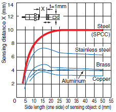
Sensing Object Material
The sensing distance varies greatly depending on the material of the sensing object. Study the engineering data for the influence of sensing object material and size and select a distance with sufficient leeway.
In general, if the sensing object is a non-magnetic metal (for example, aluminum), the sensing distance decreases.
Example: E2-X10D[]
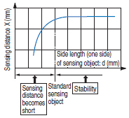
Size of Sensing Object
In general, if the object is smaller than the standard sensing object, the sensing distance decreases.
Design the setup for an object size that is the same or greater than the standard sensing object size from the graphs showing the sensing object size and sensing distance.
When the size of the standard sensing object is the same or less than the size of the standard sensing object, select a sensing distance with sufficient leeway.
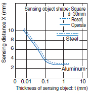
Thickness of Sensing Object
The thickness of ferrous metals (iron, nickel, etc.) must be 1 mm or greater.
For non-magnetic metal, a sensing distance equivalent to a magnetic body can be obtained when the coating thickness is 0.01 mm or less. With pulseresponse models (e.g., E2V), however, the characteristics may vary. Be sure to check the catalog information for the relevant model.
When the coating is extremely thin and is not conductive, such as a vacuum deposited film, detection is not possible.
Influence of Plating
If the sensing object is plated, the sensing distance will change (see the table below).
Effect of Plating (Typical)
(Reference values: Percent of non-plated sensing distance)
| Thickness and base material of plating | Steel | Brass |
| No plating | 100 | 100 |
| Zn 5 to 15 μm | 90 to 120 | 95 to 105 |
| Cd 5 to 15 μm | 100 to 110 | 95 to 105 |
| Ag 5 to 15 μm | 60 to 90 | 85 to 100 |
| Cu 10 to 20 μm | 70 to 95 | 95 to 105 |
| Cu 5 to 15 μm | - | 95 to 105 |
| Cu (5 to 10 μm) + Ni (10 to 20 μm) | 70 to 95 | - |
| Cu (5 to 10 μm) + Ni (10 μm) + Cr (0.3 μm) | 75 to 95 | - |
Mutual Interference
Mutual interference refers to a state where a Sensor is affected by magnetism (or static capacitance) from an adjacent Sensor and the output is unstable.
One means of avoiding interference when mounting Proximity Sensors close together is to alternate Sensors with different frequencies. The model tables indicate whether different frequencies are available. Please refer to the tables.
When Proximity Sensors with the same frequency are mounted together in a line or face-to-face, they must be separated by a minimum distance. For details, refer to Mutual Interference in the Safety Precautions for individual Sensors.
Power Reset Time
A Sensor is ready for detection within 100 ms after turning ON the power. If the load and Sensor are connected to separate power supplies, design the system so that the Sensor power turns ON first.
Turning OFF the Power
An output pulse may be generated when the power is turned OFF, so design the system so that the load or load line power turns OFF first.
Influence of Surrounding Metal
The existence of a metal object other than the sensing object near the sensing surface of the Proximity Sensor will affect detection performance, increase the apparent operating distance, degrade temperature characteristics, and cause reset failures. For details, refer to the influence of surrounding metal table in Safety Precautions for individual Sensors. Particularly the distance m that separates a metal surface that faces the Sensor's sensing surface will influence performance, such as shortening the sensing distance.
The values in the table are for the nuts provided with the Sensors.
Changing the nut material will change the influence of the surrounding metal.
Power Transformers
Be sure to use an insulated transformer for a DC power supply. Do not use an auto-transformer (single-coil transformer).
Precautions for AC 2-Wire/DC 2-Wire Sensors
Surge Protection
Although the Proximity Sensor has a surge absorption circuit, if there is a device (motor, welder, etc.) that causes large surges near the Proximity Sensor, insert a surge absorber near the source of the surges.
Influence of Leakage Current
Even when the Proximity Sensor is OFF, a small amount of current runs through the circuit as leakage current.
For this reason, a small current may remain in the load (residual voltage in the load) and cause load reset failures. Verify that this voltage is lower than the load reset voltage (the leakage current is less than the load reset current) before using the Sensor.
Using an Electronic Device as the Load for an AC 2-Wire Sensor
When using an electronic device, such as a Timer, some types of devices use AC half-wave rectification. When a Proximity Sensor is connected to a device using AC half-wave rectification, only AC half-wave power will be supplied to the Sensor. This will cause the Sensor operation to be unstable. Also, do not use a Proximity Sensor to turn the power supply ON and OFF for electronic devices that use DC half-wave rectification. In such a case, use a relay to turn the power supply ON and OFF, and check the system for operating stability after connecting it.
Examples of Timers that Use AC Half-wave Rectification
Timers: H3Y, H3YN, H3RN, H3CA-8, and H3CR (-A, -A8, -AP, -F, -G)
Countermeasures for Leakage Current (Examples)
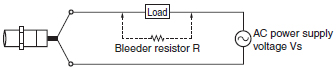
AC 2-Wire Sensors
Connect a bleeder resistor to bypass the leakage current flowing in the load so that the current flowing through the load is less than the load reset current.
When using an AC 2-Wire Sensor, connect a bleeder resistor so that the Proximity Sensor current is at least 10 mA, and the residual load voltage when the Proximity Sensor is OFF is less than the load reset voltage.
Calculate the bleeder resistance and allowable power using the following equation.
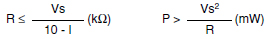
P: Watts of bleeder resistance (the actual number of watts used should be several times this number)
I: Load current (mA)
It is recommend that leeway be included in the actual values used.
For 100 VAC, use 10 kΩ or less and 3 W (5 W) or higher, and for 200 VAC, use 20 kΩ or less and 10 W (20 W) or higher. If the effects of heat generation are a problem, use the number of watts in parentheses ( ) or higher.
DC 2-Wire Sensors
Connect a bleeder resistor to bypass the leakage current flowing in the load, and design the load current so that
(leakage current) × (load input impedance) < reset voltage.
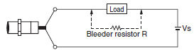
Calculate the bleeder resistance and allowable power using the following equation.
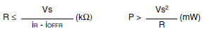
P: Watts of bleeder resistance (the actual number of watts used should be several times this number)
iR: Leakage current of Proximity Sensor (mA)
iOFFR: Load reset current (mA)
It is recommend that leeway be included in the actual values used.
For 12 VDC, use 15 kΩ or less and 450 mW or higher, and for 24 VDC, use 30 kΩ or less and 0.1 W or higher.
Loads with Large Inrush Current
Loads, such as lamps or motors, that cause a large inrush current* will weaken or damage the switching element. In this situation, use a relay.
* E2K, TL-N[]Y: 1 A or higher
Noise
Countermeasures for noise depend on the path of noise entry, frequency components, and wave heights. Typical measures are as given in the following table.
| Type of noise | Noise intrusion path and countermeasure | |
| Before countermeasure | After countermeasure | |
| Common mode noise (inverter noise) (Common noise applied between the mounting board and the +V and 0-V lines, respectively.) | Noise enters from the noise source through the frame (metal). | 1. Ground the inverter motor (to 100 Ω or less) |
 | 2. Ground the noise source and the power supply (0-V side) through a capacitor (film capacitor, 0.22 μF, 630 V). | |
| 3. Insert an insulator (plastic, rubber, etc.) between the Sensor and the mounting plate (metal). | ||
 | ||
| Radiant noise (Ingress of high-frequency electromagnetic waves directly into Sensor, from power line, etc.) | Noise propagates through the air from the noise source and directly enters the Sensor. | ・ Insert a shield (copper) plate between the Sensor and the noise source e.g., a switching power supply). |
 | ・ Separate the noise source and the Sensor to a distance where noise does not affect operation. | |
 | ||
| Power line noise (Ingress of electromagnetic induction from high-voltage wires and switching noise from the switching power supply) | Noise enters from the power line. | ・ Insert a capacitor (e.g., a film capacitor), noise filter (e.g., ferrite core or insulated transformer), or varistor in the power line. |
 |  | |
Mounting
Mounting the Sensor
When mounting a Sensor, do not tap it with a hammer or otherwise subject it to excessive shock. This will weaken water resistance and may damage the Sensor. If the Sensor is being secured with bolts, observe the allowable tightening torque. Some models require the use of toothed washers.
For details, refer to the mounting precautions in Precautions for Correct Use in individual product information.
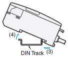
Mounting/Removing Using DIN Track (Example for E2CY)
Mounting
1. Insert the front of the Sensor into the special Mounting Bracket (included) or DIN Track.
2. Press the rear of the Sensor into the special Mounting Bracket or DIN Track.
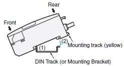
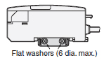
When mounting the side of the Sensor using the special Mounting Bracket, first secure the Amplifier Unit to the special Mounting Bracket, and then mount the special Mounting Bracket with M3 screws and flat washers with a diameter of 6 mm maximum.
Removing
While pressing the Amplifier Unit in the direction of 3., lift the fiber plug in the direction of 4. for easy removal without a screwdriver.
Set Distance
The sensing distance may vary due to fluctuations in temperature and voltage. When mounting the Sensor, it is recommend that installation be based on the set distance.
Wiring
AND/OR Connections for Proximity Sensors
Both series and parallel connections are possible. However, some models require connection via a relay. Please refer to the table below. The number of units that can be connected, the connection method, and conditions vary depending on the sensor type (DC 2-wire, AC 2-wire, DC 3-wire) and series. For connection information, please refer to the "Connection Details".
Necessity of connection via a relay
Connection details
Note: When AND/OR connections are used with Proximity Sensors, the effects of erroneous pulses or leakage current may prevent use. Verify
that there are no problems before use.
* E2E series DC 3-wire model has been discontinued at March 2022.
Table 1: DC 2-wire (Model example: E2E NEXT Series E2E-X[]D[][][])
Table 2: DC 2-wire (Model example: E2E-X[]D[]-U)
Table 3: AC 2-wire
Table 4: DC 3-wire NPN
Table 5: DC 3-wire PNP
Cable
The insulated part of the cable terminal is used for our internal characteristic inspections. This section is not covered by our warranty. Please cut and process the insulated part of the cable terminal (brown, blue, black, etc.) before use.
Extending Cable Length
The cable of a Built-in Amplifier Sensor can be extended to a maximum length of 200 m with each of the standard cables (excluding some models).
For Separate Amplifier Sensors (E2C-EDA, E2C, E2J, E2CY-SD), refer to the specific precautions for individual products.
Bending the Cable
If you need to bend the cable, we recommend a bend radius that is at least 3 times the outer diameter of the cable. (For coaxial, shielded and robot cables, at least 5 times the outer diameter of the cable is recommended.) The minimum bending radius is specified as the radius of the inside surface of the cable bend.
Cable Tensile Strength
In general, do not subject the cable to a tension greater than that indicated in the following table.
| Cable diameter | Tensile strength |
| Less than 4 mm | 30 N max. |
| 4 mm min. | 50 N max. |
Note: Do not subject a shielded cable or coaxial cable to tension.
Separation from High Voltage (Wiring Method)
Do not lay the cables for the Sensor together with high-voltage lines or power lines. Placing them in the same conduit or duct may cause damage or malfunction due to induction interference. As a general rule, wire the Sensor in a separate system, use an independent metal conduit, or use shielded cable.
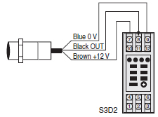
Example of Connection with S3D2 Sensor Controller
DC 2-Wire Sensors
Using the S3D2 Sensor Controller
Operation can be reversed with the signal input switch on the S3D2.
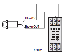
Connecting to a Relay Load
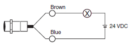
Note: DC 2-Wire Sensors have a residual voltage of 3 V. Check the operating voltage of the relay before use.
The residual voltage of the E2E-XD-M1J-T is 5 V.
DC 3-Wire Sensors
Operation can be reversed with the signal input switch on the S3D2.
Operating Environment
Water Resistance
Do not use the Sensor in water, rain, or outdoors.
Ambient Conditions
Do not use the Sensor in the following environments.
Doing so may cause malfunction or failure of the Sensor.
1. To maintain operational reliability and service life, use the Sensor only within the specified temperature range and do not use it outdoors.
2. The Sensor has a water resistant structure, however, attaching a cover to prevent direct contact with water will help improve reliability and prolong product life.
3. Avoid using the Sensor where there are chemical vapors, especially strong alkalis or acids (nitric acid, chromic acid, or hot concentrated sulfuric acid).
4. At low temperatures (0°C or less), the vinyl cable will harden and the wires may break if the cable is bent. Do not bend a Standard or Robot Cable at low temperature.
Maintenance and inspection
Periodic Inspection
To ensure long-term stable operation of the Proximity Sensor, inspect for the following on a regular basis. Conduct these inspections also for control devices.
1. Shifting, loosening, or deformation of the sensing object and Proximity Sensor mounting
2. Loosening, bad contact, or wire breakage in the wiring and connections
3. Adherence or accumulation of metal powder
4. Abnormal operating temperature or ambient conditions
5. Abnormal indicator flashing (on setting indicator types)
Disassembly and Repair
Do not under any circumstances attempt to disassemble or repair the product.
Quick Failure Check
You can conveniently check for failures by connecting the E39-VA Handy Checker to check the operation of the Sensor.