(Unit: mm)
E32 Series
Fiber Sensors
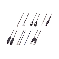
OMRON's Fiber Sensors continue to support an increasing range of applications.
- Features
- Lineup
- Specifications
- Dimensions
- Catalog
last update: December 22, 2025
Standard Installation
Threaded Models
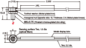
Through-beam Fiber Units (Set of 2)
E32-T11N 2M (Free Cutting)
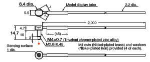
E32-T11R 2M (Free Cutting)

E32-LT11 2M (Free Cutting)
E32-LT11R 2M (Free Cutting)

Reflective Fiber Units
E32-C31N 2M (Free Cutting)
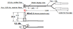
M3 nuts (Nickel-plated brass)
Washers (Nickel-plated brass) provided (2 of each)
E32-C91N 2M (Free Cutting)
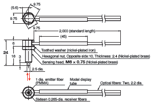
Note: There is a white line on the emitter fiber.
E32-D21R 2M (Free Cutting)

E32-C31 2M (Free Cutting)
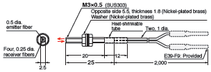
Note: There is a white line on the emitter fiber.
E32-C31M 1M (Free Cutting)

* The Fiber Attachments that are provided were specially designed for this Fiber Unit.
E39-F9 cannot be attached.
E32-D211R 2M (Free Cutting)

E32-D11R 2M (Free Cutting)

E32-CC200 2M (Free Cutting)
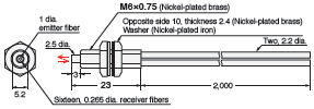
Note: There is a white line on the emitter fiber.
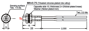
E32-LD11 2M (Free Cutting)
E32-LD11R 2M (Free Cutting)
Hex-shaped Models
Through-beam Fiber Units
E32-LT11N 2M (Free Cutting)
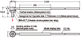
E32-T11N 2M (Free Cutting)

Reflective Fiber Units
E32-LD11N 2M (Free Cutting)
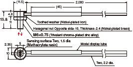
E32-C21N 2M (Free Cutting)
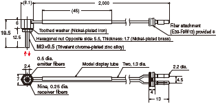
Note: There is a white line on the emitter fiber.
* Applicable Fiber Amplifier Units: E3NX-FA, E3NX-CA, and E3X-HD.
Use the enclosed E39-F9-7 Fiber Attachment for other models, such as the E3X-SD, E3X-NA, and other models that have an 8-mm space between the emitter and receiver fiber insertion holes.
E32-D21N 2M (Free Cutting)
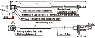
* Applicable Fiber Amplifier Units: E3NX-FA, E3NX-CA, and E3X-HD.
Use the enclosed E39-F9-7 Fiber Attachment for other models, such as the E3X-SD, E3X-NA, and other models that have an 8-mm space between the emitter and receiver fiber insertion holes.
E32-C91N 2M (Free Cutting)
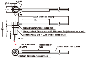
Note: There is a white line on the emitter fiber.
Retro-reflective Fiber Units (With M.S.R. Function)
E32-LR11NP 2M (Free Cutting)
E39-RP1
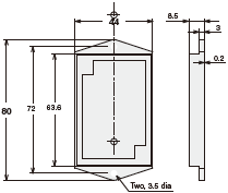
Material:
[Reflective surface] Methacrylate resin
[Back] ABS
Cylindrical Models
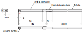
Through-beam Fiber Units (Set of 2)
E32-T223R 2M (Free Cutting)

E32-T22B 2M (Free Cutting)

E32-T12R 2M (Free Cutting)

E32-T14LR 2M (Free Cutting)
Reflective Fiber Units
E32-D22B 2M (No Cutting)
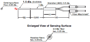
* Attached with adhesive and cannot be removed.
E32-D43M 1M (No Cutting)

* Attached with adhesive and cannot be removed.
E32-D22R 2M (Free Cutting)

E32-D221B 2M (Free Cutting)

E32-D32L 2M (Free Cutting)

Note: There is a yellow dotted line on the Emitter fiber.
E32-D33 2M (Free Cutting)

E32-D14LR 2M (Free Cutting)
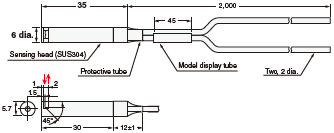
Hex-shaped Models
Through-beam Fiber Units
E32-LT11N 2M (Free Cutting)
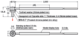
E32-T11N 2M (Free Cutting)

Reflective Fiber Units
E32-LD11N 2M (Free Cutting)
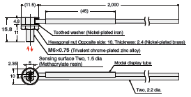
E32-C21N 2M (Free Cutting)
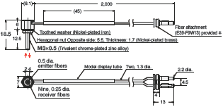
* Applicable Fiber Amplifier Units: E3NX-FA, E3NX-CA, E3X-HD, and E3X-DA-S.
Use the enclosed E39-F9-7 Fiber Attachment for other models, such as the E3X-MDA with two channels, and for the E3X-
SD, E3X-NA, and other models that have an 8-mm space between the emitter and receiver fiber insertion holes.
E32-D21N 2M (Free Cutting)
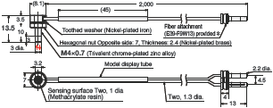
Use the enclosed E39-F9-7 Fiber Attachment for other models, such as the E3X-MDA with two channels, and for the E3X-
SD, E3X-NA, and other models that have an 8-mm space between the emitter and receiver fiber insertion holes.
E32-C11N 2M (Free Cutting)
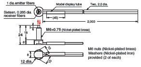
Note: There is a white line on the emitter fiber.
Retro-reflective Fiber Units (With M.S.R. Function)
E32-LR11NP 2M (Free Cutting)
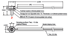
E39-RP1
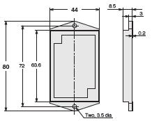
Material:
[Reflective surface] Methacrylate resin
[Back] ABS
Saving Space
Flat Models
Through-beam Fiber Units (Set of 2)
E32-T15XR 2M (Free Cutting)

2. Four, M2 × 8 stainless steel countersunk mounting screws are provided.
E32-T25XR 2M (Free Cutting)

Note: 1. Set of two symmetrically shaped Fiber Units.
2. Four, M2 × 8 stainless steel countersunk mounting screws are provided.
E32-T15YR 2M (Free Cutting)
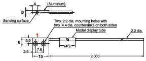
2. Four, M2 × 8 stainless steel countersunk mounting screws are provided.
E32-T25YR 2M (Free Cutting)
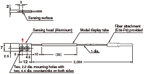
Note: 1. Set of two symmetrically shaped Fiber Units.
2. Four, M2 × 8 stainless steel countersunk mounting screws are provided.
E32-T15ZR 2M (Free Cutting)

2. Four, M2 × 8 stainless steel countersunk mounting screws are provided.
E32-T25ZR 2M (Free Cutting)

Note: 1. Set of two symmetrically shaped Fiber Units.
2. Four, M2 × 8 stainless steel countersunk mounting screws are provided.
E32-LT35Z 2M (Free Cutting)
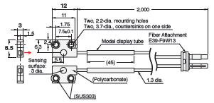
Note: 1. Set of two symmetrically shaped Fiber Units.
2. Four, M2 x 8 stainless-steel, pan-head mounting screws,
four spring washers, four flat washers, and four nuts are provided.
Reflective Fiber Units
E32-D15XR 2M (Free Cutting)

Note: Two, M2 × 8 stainless steel countersunk mounting screws are provided.
E32-D25XR 2M (Free Cutting)
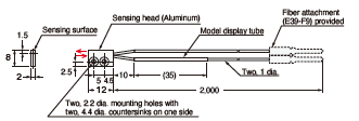
Note: Two, M2 × 8 stainless steel countersunk mounting screws are provided.
E32-D15YR 2M (Free Cutting)
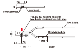
Note: Two, M2 × 8 stainless steel countersunk mounting screws are provided.
E32-D25YR 2M (Free Cutting)
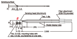
Note: Two, M2 × 8 stainless steel countersunk mounting screws are provided.
E32-D15ZR 2M (Free Cutting)
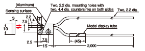
Note: Two, M2 × 8 stainless steel countersunk mounting screws are provided.
E32-D25ZR 2M (Free Cutting)
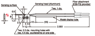
Note: Two, M2 × 8 stainless steel countersunk mounting screws are provided.
Sleeve Models (Close-range Detection)
Through-beam Fiber Units (Set of 2)
E32-T24R 2M (Free Cutting)
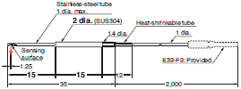
E32-T24E 2M (Free Cutting)

E32-T33 1M (Free Cutting)

E32-T21-S1 2M (Free Cutting)

E32-TC200BR 2M (Free Cutting)

Reflective Fiber Units
E32-D24R 2M (Free Cutting)
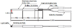
E32-D24-S2 2M (Free Cutting)

E32-D43M 1M (No Cutting)

* Attached with adhesive and cannot be removed.
E32-D331 2M (No Cutting)

* Attached with adhesive and cannot be removed.
E32-D33 2M (Free Cutting)

E32-D32-S1 0.5M (No Cutting)

* Attached with adhesive and cannot be removed.
E32-D31-S1 0.5M (No Cutting)

* Attached with adhesive and cannot be removed.
E32-DC200F4R 2M (Free Cutting)

E32-D22-S1 2M (Free Cutting)

E32-D21-S3 2M (Free Cutting)

E32-DC200BR 2M (Free Cutting)
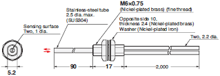
E32-D25-S3 2M (Free Cutting)

Beam Improvements
Small-Spot, Reflective (Minute Object Detection)
Reflective Fiber Units
E32-C42 1M (No Cutting) + E39-F3A

* Attached with adhesive and cannot be removed.
Note: There is a white tube on the emitter fiber.
E39-F3A

Material: Aluminum for body and optical glass for lens.
Note: This is the Lens Unit for the E32-C42.
E32-C42 1M (No Cutting) + E39-F17

* Attached with adhesive and cannot be removed.
Note: There is a white tube on the emitter fiber.
E39-F17

Material: Aluminum for body and optical glass for lens.
E32-C31 2M (Free Cutting) + E39-F3C

Note: There is a white line on the emitter fiber.
E39-F3C

Material: Aluminum for body and optical glass for lens.
Note: This is the Lens Unit for the E32-C31 and E32-C31N.
E32-C21N 2M (Free Cutting) + E39-F3C

Note: There is a white line on the emitter fiber.
E32-C42S 1M (No Cutting)

* Attached with adhesive and cannot be removed.
Note: There is a white tube on the emitter fiber.
E32-L15 2M (Free Cutting)
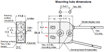
Note: There is a white tube on the emitter fiber.
E32-C41 1M (No Cutting) + E39-F3A-5

* Attached with adhesive and cannot be removed.
Note: There is a white tube on the emitter fiber.
E39-F3A-5

Material: Aluminum for body and optical glass for lens
Note: This is a Lens Unit for the E32-C41, E32-C31 and E32-C31N.
E32-C31 2M (Free Cutting) + E39-F3A-5

Note: There is a white line on the emitter fiber.
E32-C21N 2M (Free Cutting) + E39-F3A-5
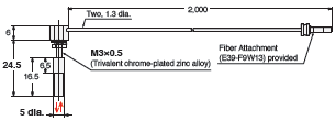
Note: There is a white line on the emitter fiber.
E32-C41 1M (No Cutting) + E39-F3B

* Attached with adhesive and cannot be removed.
Note: There is a white tube on the emitter fiber.
E39-F3B

Material: Aluminum for body and optical glass for lens
Note: This is a Lens Unit for the E32-C41, E32-C31 and E32-C31N.
E32-C31 2M (Free Cutting) + E39-F3B

Note: There is a white line on the emitter fiber.
E32-C21N 2M (Free Cutting) + E39-F3B
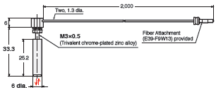
Note: There is a white line on the emitter fiber.
E32-CC200 2M (Free Cutting) + E39-F18

Note: There is a white line on the emitter fiber.
E39-F18

Material: Aluminum for body and optical glass for lens
Note: This is a Lens Unit for the E32-C91N and E32-CC200.
E32-C91N 2M (Free Cutting) + E39-F18
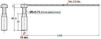
Note: There is a white line on the emitter fiber.
High-power Beam (Long-distance Installation, Dust-resistant)
Fiber only
Through-beam Fiber Units (Set of 2)
E32-LT11N 2M (Free Cutting)
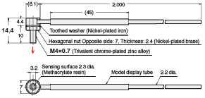
E32-T17L 10M (Free Cutting)
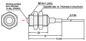
E32-LT11 2M (Free Cutting)
E32-LT11R 2M (Free Cutting)

E32-T14 2M (Free Cutting)
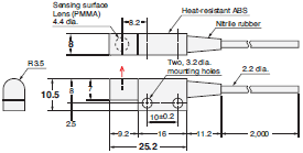
Reflective Fiber Units
E32-D16 2M (Free Cutting)

Lens (to 70°C)
Lens Units (Set of 2)
E39-F1

Material: Brass for the body and optical glass for the lens itself.
Note: Two per set.
E39-F16

Material: SUS303 for the body and optical glass for the lens itself.
Note: Two per set.
E39-F2

Material: Brass for the body and optical glass for the lens itself.
Note: Two per set.
Through-beam Fiber Units (Set of 2)
E32-T11N 2M (Free Cutting) + E39-F1

E32-T11R 2M (Free Cutting) + E39-F1

E32-T11 2M (Free Cutting) + E39-F1

E32-T11N 2M (Free Cutting) + E39-F16
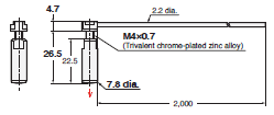
E32-T11R 2M (Free Cutting) + E39-F16

E32-T11 2M (Free Cutting) + E39-F16

E32-T11R 2M (Free Cutting) + E39-F2

E32-T11 2M (Free Cutting) + E39-F2

Lens (to 200°C)
Lens Units (Set of 2)
E39-F1

Material: Brass for the body and optical glass for the lens itself.
Note: Two per set.
E39-F16

Material: SUS303 for the body and optical glass for the lens itself.
Note: Two per set.
E39-F2

Material: Brass for the body and optical glass for the lens itself.
Note: Two per set.
E39-F1-33

Material: Brass for the body and optical glass for the lens itself.
Note 1: Two per set.
Note 2: This is the Lens Unit for the E32-T51.
Through-beam Fiber Units (Set of 2)
E32-T51R 2M (Free Cutting) + E39-F1

E32-T81R-S 2M (No Cutting) + E39-F1

E32-T61-S 2M (No Cutting) + E39-F1

E32-T51R 2M (Free Cutting) + E39-F16

E32-T81R-S 2M (No Cutting) + E39-F16

E32-T61-S 2M (No Cutting) + E39-F16

E32-T51R 2M (Free Cutting) + E39-F2

E32-T81R-S 2M (No Cutting) + E39-F2

E32-T61-S 2M (No Cutting) + E39-F2

E32-T51 2M (Free Cutting) + E39-F1-33

E32-T51 2M (Free Cutting) + E39-F16

Narrow View (Detection Across clearance)
Through-beam Fiber Units (Set of 2)
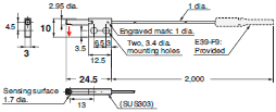
E32-A03 2M (Free Cutting)
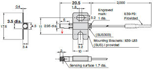
Note: Use the engraved surface and its opposing surface as installation (reference) surfaces.
E32-A03-1 2M (Free Cutting)
2. Set of two symmetrically shaped Fiber Units.
E32-A04 2M (Free Cutting)
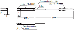
Note: Use the engraved surface and its opposing surface as installation (reference) surfaces.
E32-T24SR 2M (Free Cutting)
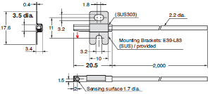
E32-T24S 2M (Free Cutting)
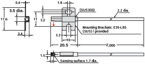
E32-T22S 2M (Free Cutting)

Detection without Background Interference
Limited-reflective Fiber Units
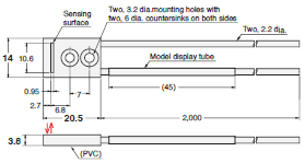
E32-L16-N 2M (Free Cutting)
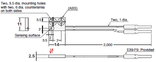
E32-L24S 2M (Free Cutting)
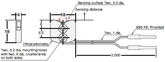
E32-L25L 2M (Free Cutting)
Transparent Object Detection
Retro-reflective
Retro-reflective Fiber Units (With M.S.R. Function)
E32-LR11NP 2M (Free Cutting)
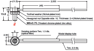
E39-RP1
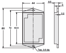
Material:
[Reflective surface] Methacrylate resin
[Back] ABS
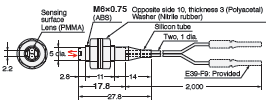
E32-R16 2M (Free Cutting)
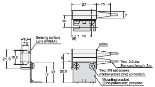
E39-R1 (Provided)
Material:
[Reflective surface] Methacrylate resin
[Back] ABS
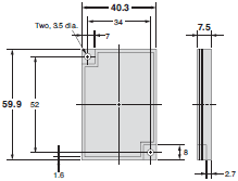
E32-R21 2M (Free Cutting)
E39-R3 (Provided)
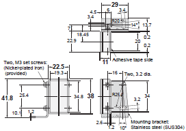
Material:
[Reflective surface] Methacrylate resin
[Back] ABS
Limited-reflective (Glass Detection)
Limited-reflective Fiber Units
E32-L24S 2M (Free Cutting)
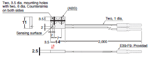
E32-L16-N 2M (Free Cutting)
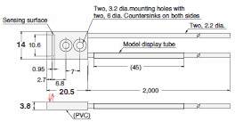
E32-A08 2M (Free Cutting)
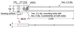
E32-A12 2M (Free Cutting)
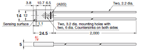
E32-L25L 2M (Free Cutting)
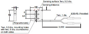
E32-A09 2M (Free Cutting)

Environmental Immunity
Chemical-resistant, Oil-resistant
Through-beam Fiber Units (Set of 2)
E32-T11NF 2M (Free Cutting)
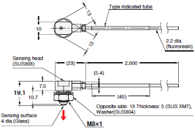
E32-T11NFS 2M (Free Cutting)
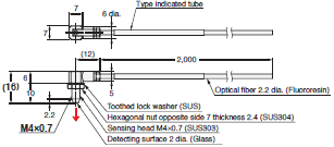
E32-T12F 2M (Free Cutting)

E32-T11F 2M (Free Cutting)

E32-T14F 2M (Free Cutting)

E32-T51F 2M (Free Cutting)

Reflective Fiber Units
E32-L11FP 2M (Free Cutting)
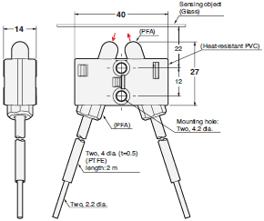
E32-L11FS 2M (Free Cutting)
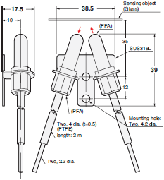
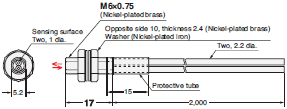
E32-D12F 2M (Free Cutting)

E32-D11U 2M (Free Cutting)
Bending-resistant, Disconnection-resistant
Through-beam Fiber Units (Set of 2)
E32-T22B 2M (Free Cutting)

E32-T21 2M (Free Cutting)

E32-T11 2M (Free Cutting)

E32-T25XB 2M (Free Cutting)

2. Four, M2 × 8 stainless steel countersunk mounting screws are provided.
E39-F32C 1M

Note: Saddles (four, trivalent chromate-plated iron) are provided.
Limited-reflective Fiber Units
E32-D22B 2M (No Cutting)
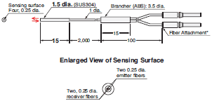
* Attached with adhesive and cannot be removed.
E32-D21 2M (Free Cutting)
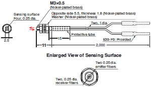
E32-D221B 2M (Free Cutting)

E32-D21B 2M (Free Cutting)

E32-D11 2M (Free Cutting)
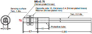
E32-D25XB 2M (Free Cutting)

Note: Two, M2×8 stainless steel countersunk mounting screws are provided.
E39-F32A 1M/E39-F32C 1M/E39-F32D 1M
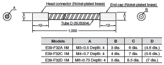
Note: Saddles (two (four for the E39-F32C 1M), trivalent chromate-plated iron) are provided.
Heat-resistant
Through-beam Fiber Units (Set of 2)
E32-T51R 2M (Free Cutting)

E32-T51 2M (Free Cutting)

E32-T54 2M (Free Cutting)
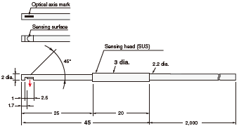
E32-T81R-S 2M (No Cutting)

Note: The maximum allowable temperatures for sections A and B are 200°C and 110°C, respectively. The section inserted into the Amplifier Unit (indicated by *) must be maintained within the Amplifier Unit's operating temperature range.
E32-T84S-S 2M (No Cutting)
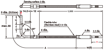
Note: The maximum allowable temperatures for sections A and B are 200°C and 110°C, respectively. The section inserted into the Amplifier Unit (indicated by *) must be maintained within the Amplifier Unit's operating temperature range.
E32-T64-2 2M (No Cutting)
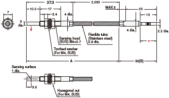
Note: The maximum allowable temperatures for sections A and B are 300°C and 110°C, respectively. The section inserted into the Amplifier Unit (indicated by *) must be maintained within the Amplifier Unit's operating temperature range.
E32-T61-S 2M (No Cutting)

Note: The maximum allowable temperatures for sections A and B are 350°C and 110°C, respectively. The section inserted into the Amplifier Unit (indicated by *) must be maintained within the Amplifier Unit's operating temperature range.
Reflective Fiber Units
E32-D51R 2M (Free Cutting)
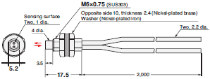
E32-D51 2M (Free Cutting)
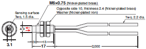
E32-D81R-S 2M (No Cutting)
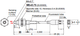
Note: The maximum allowable temperatures for sections A and B are 200°C and 110°C, respectively. The section inserted into the Amplifier Unit (indicated by *) must be maintained within the Amplifier Unit's operating temperature range.
E32-A08H2 2M (No Cutting)
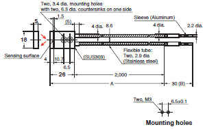
Note: The maximum allowable temperatures for sections A and B are 300°C and 110°C, respectively. The section inserted into the Amplifier Unit (indicated by *) must be maintained within the Amplifier Unit's operating temperature range.
E32-L64 2M (No Cutting)
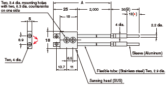
Note: The maximum allowable temperatures for sections A and B are 300°C and 110°C, respectively. The section inserted into the Amplifier Unit (indicated by *) must be maintained within the Amplifier Unit's operating temperature range.
E32-L86 2M (No Cutting)
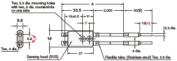
Note: The maximum allowable temperatures for sections A and B are 200°C and 110°C, respectively. The section inserted into the Amplifier Unit (indicated by *) must be maintained within the Amplifier Unit's operating temperature range.
E32-A09H2 2M (No Cutting)

Note: The maximum allowable temperatures for sections A and B are 300°C and 110°C, respectively. The section inserted into the Amplifier Unit (indicated by *) must be maintained within the Amplifier Unit's operating temperature range.
E32-D611-S 2M (No Cutting)
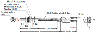
Note: The maximum allowable temperatures for sections A and B are 350°C and 110°C, respectively.
The section inserted into the Amplifier Unit (indicated by *) must be maintained within the Amplifier Unit's operating temperature range.
E32-D61-S 2M (No Cutting)
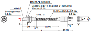
Note: The maximum allowable temperatures for sections A and B are 350°C and 110°C, respectively. The section inserted into the Amplifier Unit (indicated by *1) must be maintained within the Amplifier Unit's operating temperature range.
*2. The diameter is 6 dia. if the fiber length exceeds 10 m.
*3. The length is 10 if the fiber length exceeds 10 m.
E32-D73-S 2M (No Cutting)
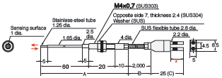
Note: The maximum allowable temperatures for sections A, B, and C are 400°C, 300°C, and 110°C, respectively. The section inserted into the Amplifier Unit (indicated by *) must be maintained within the Amplifier Unit's operating temperature range.
Special Applications
Area Beam (Area Detection)
Through-beam Fiber Units (Set of 2)
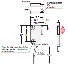
E32-T16PR 2M (Free Cutting)
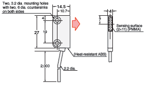
* Stickers with slits of widths 0.5 and 1 mm (2 of each) provided.
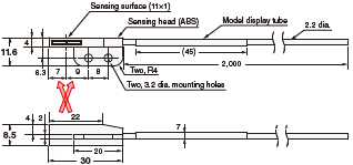
E32-T16JR 2M (Free Cutting)
E32-A13 2M (Free Cutting)
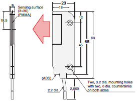
E32-T16WR 2M (Free Cutting)
E32-G16
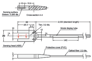
Reflective Fiber Units
E32-D36P1 2M (Free Cutting)
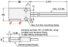
Liquid-level Detection
E32-A01 5M (Free Cutting)

* Mount the holder at the appropriate position based on the actual tube diameter (1/8, 1/4, 3/8 inch).
Note: Two nylon bands are provided.
E32-L25T 2M (Free Cutting)

Note: Two nylon bands and one anti-reflector are provided.
E32-D36T 2M (Free Cutting)

E32-D82F1 4M (Free Cutting)

* The 2-m section of optical fiber on the Amplifier unit side is plastic and therefore allows free cutting.
Note: The maximum allowable temperature is 200°C for section A and 85°C for section B.
Vacuum-resistant
Through-beam Fiber Units (Set of 2)
E32-T51V 1M (No Cutting)

E32-T51V 1M (No Cutting) + E39-F1V

E39-F1V

E32-T84SV 1M (No Cutting)
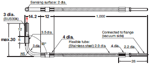
E32-T10V 2M (Free Cutting)

E32-VF4
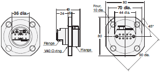
Note 1. Mount the Flange so that the V40 O-ring is on the atmospheric-pressure side of the vacuum chamber wall.
Note 2. Mounting-hole dimensions: 38 dia. ±0.5 mm
Note 3. The maximum tightening torque is 9.8 Nm.
Note 4. A V40 O-ring is provided.
E32-VF1
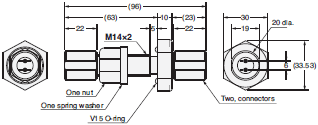
Note 1. Mount the Flange so that the V15 O-ring is on the atmospheric-pressure side of the vacuum chamber wall.
Note 2. Mounting-hole dimensions: 14.5 dia. ±0.2 mm
Note 3. The maximum tightening torque is 14.7 Nm for the clamp nut and 1.5 Nm for the connector.
Note 4. A V15 O-ring, nut, spring washer, two connectors, and four O-rings for the fibers are provided.
FPD, Semiconductors, and Solar Cells
Limited-reflective Fiber Units
E32-L16-N 2M (Free Cutting)
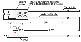
E32-A08 2M (Free Cutting)
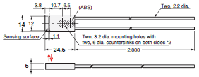
E32-A08H2 2M (No Cutting)
Note: The maximum allowable temperatures is 300°C for sections A and 110°C for section B (section inserted into Amplifier Unit).
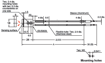
E32-A12 2M (Free Cutting)
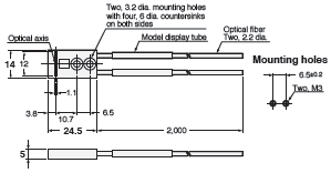
E32-A09 2M (Free Cutting)
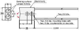
E32-A09H2 2M (No Cutting)
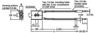
Note: The maximum allowable temperatures for sections A and B are 300°C and 110°C, respectively. The section inserted into the Amplifier Unit (indicated by *) must be maintained within the Amplifier Unit's operating temperature range.
E32-L11FP 2M (Free Cutting)
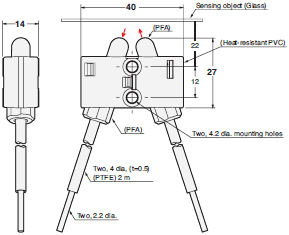
E32-L11FS 2M (Free Cutting)
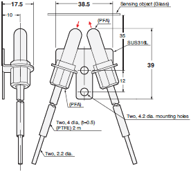
Through-beam Fiber Units (Set of 2)
E32-A03 2M (Free Cutting)
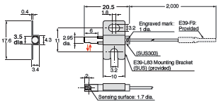
Note: Use the engraved surface and its opposing surface as installation (reference) surfaces.
E32-A03-1 2M (Free Cutting)
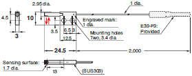
Note 1. Use the engraved surface and its opposing surface as installation (reference) surfaces.
Note 2. Set of two symmetrical parts.
E32-A03-2 2M (Free Cutting)
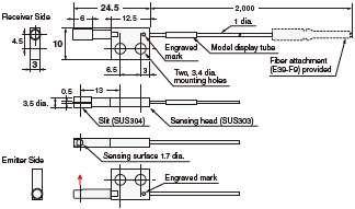
Note: Use the engraved surface and its opposing surface as installation (reference) surfaces.
E32-A04 2M (Free Cutting)
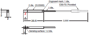
Note: Use the engraved surface and its opposing surface as installation (reference) surfaces.
E32-A04-1 2M (Free Cutting)
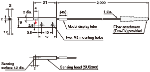
E32-A04-8 2M (Free Cutting)
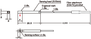
Note: Use the engraved surface and its opposing surface as installation (reference) surfaces.
E32-T24SR 2M (Free Cutting)
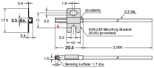
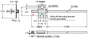
E32-T24S 2M (Free Cutting)
last update: December 22, 2025