| Time range
setting |
0.1 s | 1 s | 10 s | 1 min | 10 min | 1 h | 10 h | 100 h |
|---|---|---|---|---|---|---|---|---|
| Set time
range |
0.1 to 1.2 s | 1 to 12 s | 10 to 120 s | 1 to 12 min | 10 to 120 min | 1 to 12 h | 10 to 120 h | 100 to 1,200 h |
| Scale
numbers |
12 | |||||||
Multi-range, Multi-mode Timer
Related Contents
last update: October 18, 2018
| Time range
setting |
0.1 s | 1 s | 10 s | 1 min | 10 min | 1 h | 10 h | 100 h |
|---|---|---|---|---|---|---|---|---|
| Set time
range |
0.1 to 1.2 s | 1 to 12 s | 10 to 120 s | 1 to 12 min | 10 to 120 min | 1 to 12 h | 10 to 120 h | 100 to 1,200 h |
| Scale
numbers |
12 | |||||||
Note: When the main dial is set to “0” for all settings, the output will operate instantaneously
| Power supply voltage *1 | 24 to 240 VAC/DC, 50/60 Hz *2
12 VDC *2 |
|
|---|---|---|
| Allowable voltage fluctuation
range |
24 to 240 VAC/DC: 85% to 110% of rated voltage
12 VDC: 90% to 110% of rated voltage |
|
| Power reset | Minimum power-OFF time: 0.1 s | |
| Reset voltage | 10% of rated voltage | |
| Voltage input | 24 to 240 VAC/DC
High level: 20.4 to 264 VAC/DC, Low level: 0 to 2.4 VAC/DC 12 VDC High level: 10.8 to 13.2 VDC, Low level: 0 to 1.2 VDC |
|
| Power
consumption *3 |
H3DK-M2/-S2 | At 240 VAC: 6.6 VA max. *4 |
| H3DK-M1/-S1 | At 240 VAC: 4.5 VA max. *4 | |
| H3DK-M2A/-S2A | At 12 VDC: 0.9 W max. | |
| H3DK-M1A/-S1A | At 12 VDC: 0.6 W max. | |
| Control output | Contact output:
5 A at 250 VAC with resistive load (cosφ = 1), 5 A at 30 VDC with resistive load *5, 0.15 A max. at 125 VDC with resistive load, 0.1A at 125 VDC with L/R of 7 ms. The minimum applicable load is 10 mA at 5 VDC (P reference value). Contact materials: Ag-alloy + Gold plating |
|
| Ambient operating temperature | -20 to 55°C (with no icing) | |
| Storage temperature | -40 to 70°C (with no icing) | |
| Ambient operating humidity | 25% to 85% | |
| Accuracy of operating time | ±1% of FS max. (±1% ±10 ms max. at 1.2-s range) * | |
|---|---|---|
| Setting error | ±10% of FS ±0.05 s max. * | |
| Minimum input signal width | 50 ms* (start input) | |
| Influence of voltage | ±0.5% of FS max. (±0.5% ±10 ms max. at 1.2-s range) | |
| Influence of temperature | ±2% of FS max. (±2% ±10 ms max. at 1.2-s range) | |
| Insulation resistance | 100 MΩ min. at 500 VDC | |
| Dielectric strength | Between current-carrying metal parts and exposed non-current-carrying metal parts:
2,000 VAC 50/60 Hz for 1 min. Between control output terminals and operating circuit: 2,000 VAC 50/60 Hz for 1 min. Between contacts not located next to each other: 1,000 VAC 50/60 Hz for 1 min. |
|
| Impulse withstand voltage | 24 to 240 VAC/VDC: 5 kV between power terminals, 5 kV between current-carrying
metal parts and exposed non-current-carrying metal parts 12 VDC: 1 kV between power terminals, 1.5 kV between current-carrying metal parts and exposed non-current-carrying metal parts |
|
| Noise immunity | Square-wave noise generated by noise simulator (pulse width: 100 ns/1 μs, 1-ns rise):
±1.5 kV |
|
| Static immunity | Malfunction: 4 kV, Destruction: 8 kV | |
| Vibration
resistance |
Destruction | 0.75-mm single amplitude at 10 to 55 Hz for 2 h each in 3 directions |
| Malfunction | 0.5-mm single amplitude at 10 to 55 Hz for 10 min each in 3 directions | |
| Shock
resistance |
Destruction | 1,000 m/s2 3 times each in 6 directions |
| Malfunction | 100 m/s2 3 times each in 6 directions | |
| Life
expectancy |
Mechanical | 10 million operations min. (under no load at 1,800 operations/h) |
| Electrical | 100,000 operations min. (5 A at 250 VAC, resistive load at 360 operations/h) | |
| Degree of protection | IP30 (Terminal block: IP20) | |
| Weight | Approx. 120 g | |
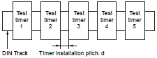
The relation between the installation pitch and the load current is shown in the following graph. (Except for the H3DK-GE)
If Timer is used under load conditions that exceed the specified values, the temperature inside the Timer will increase, reducing the life expectancy of internal parts.
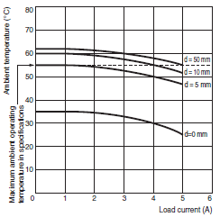
Tested Timer: H3DK-M/-S
Applied voltage: 240 VAC
Installation pitch: 0, 5, 10, and 50 mm
| Safety standards | cURus: UL 508/CSA C22.2 No. 14
EN 50274: Finger protection, back-of-hand proof EN 61812-1: Pollution degree 2, Overvoltage category III CCC: GB/T 14048.5 Pollution degree 2, Overvoltage category III * LR: Test Specification No. 1-2002 Category ENV 1.2 |
|---|---|
| EMC | (EMI) EN61812-1
Radiated Emissions: EN 55011 class B Emission AC Mains: EN 55011 class B Harmonic Current: EN 61000-3-2 Voltage Fluctuations and Flicker: EN61000-3-3 (EMS) EN61812-1 Immunity ESD: IEC61000-4-2 Immunity RF-interference: IEC61000-4-3 Immunity Burst: IEC61000-4-4 Immunity Surge: IEC61000-4-5 Immunity Conducted Disturbance: IEC61000-4-6 Immunity Voltage Dip/Interruption: IEC61000-4-11 |
* CCC certification requirements
| Recommended fuse | 0216005 (250 VAC, 5 A) manufactured by Littelfuse |
|---|---|
| Rated operating voltage Ue
Rated operating current Ie |
AC-15: Ue: 250 VAC, Ie: 3 A
AC-13: Ue: 250 VAC, Ie: 5 A DC-13: Ue: 30 VDC, Ie: 0.1 A |
| Rated insulation voltage | 250 V |
| Rated impulse withstand voltage
(altitude: 2,000 m max.) |
4 kV (at 240 VAC) |
| Conditional short-circuit current | 1,000 A |
last update: October 18, 2018
© Copyright OMRON Corporation 2007 - 2026. All Rights Reserved.