Page top

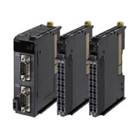
NX-CIF

NX-series Communications Interface Units

NX-CIF

Provides simplicity and flexibility in connecting serial devices to EtherCAT

General Specification

Item Specification
Enclosure Mounted in a panel.
Grounding method Ground of 100 Ω or less.
If a conductive DIN Track is used, a Communications Interface Units
is grounded through the DIN Track from the System Power Supply
Unit. If a non-conductive DIN Track is used, a Communications
Interface Units is grounded from the FG terminal.
Operating
environment
Ambient operating
temperature
0 to 55°C
Ambient operating
humidity
10% to 95% (with no condensation or icing)
Atmosphere Must be free from corrosive gases.
Ambient storage
temperature
-25 to 70°C (with no condensation or icing)
Altitude 2,000 m max.
Pollution degree 2 or less: Meets IEC 61010-2-201.
Noise immunity 2 kV on power supply line (Conforms to IEC 61000-4-4.)
Overvoltage category Category II: Meets IEC 61010-2-201.
EMC immunity level Zone B
Vibration resistance Conforms to IEC 60068-2-6.
5 to 8.4 Hz with 3.5-mm amplitude, 8.4 to 150 Hz, Acceleration of
9.8 m/s2, 100 min in X, Y, and Z directions (10 sweeps of 10 min
each = 100 min total)
Shock resistance Conforms to IEC 60068-2-27. 147 m/s2, 3 times each in X, Y, and
Z directions
Insulation resistance 20 MΩ min. between isolated circuits (at 100 VDC)
Dielectric strength 510 VAC between isolated circuits for 1 minute with leakage current
of 5 mA max.
Applicable standards * cULus: Listed (UL508), ANSI/ISA 12.12.01, EU: EN 61131-2, NK, LR, RCM,
and KC: KC Registration

* Refer to the OMRON website (http://www.ia.omron.com/) or consult your OMRON representative for the most recent applicable standards for each model.

Specifications of Individual Units

NX-CIF101

Item Specification
Number of ports 1
Communications ports RS-232C
Communications protocol No-protocol
Communications
specifications
Communications method Full duplex
Signal lines *1 ---
Baud rate [bps] *1 1,200, 2,400, 4,800, 9,600, 19,200, 38,400, 57,600,
115,200, or 230,400
Data length [bits] *1 7 or 8
Parity *1 Even, odd, or none
Start bits [bits] Always 1.
Stop bits [bits] *1 1 or 2
Flow control *1 None, RS/CS flow control, or Xon/Xoff control
Flow control target *1 Send/receive, send only, or receive only
Initial RS signal value *1 *2 ON or OFF
Number of characters to
determine the end *1 *3
0 to 10,000 (in increments of 0.1 character))
0: The end is not detected.
Maximum communications
distance [m]
15 *4
Connection configuration 1:1
I/O refreshing method Free-Run refreshing only
PDO data size [bytes] *1 Inputs or outputs: 4, 8, 12, 16, 20, 24, 28, 32, 36,
40, 44, 48, 52, 56, 60, 64, 68, 72, 76, or 80
Transmission buffering enable/disable setting *1 Enabled or disabled
Functions to back up data Provided. *5
Terminating resistance setting ---
Isolation method No isolation
Power consumption • Connected to a CPU Unit
1.10 W max.
• Connected to a Communications Coupler Unit
0.90 W max.
Weight 66 g max.
Installation orientation and restrictions Installation orientation:
• Connected to a CPU Unit: Possible in upright installation.
• Connected to a Communications Coupler Unit:
Possible in 6 orientations.
Restrictions: There are no restrictions.

*1. Setting is possible in the Unit operation settings of the Sysmac Studio.
*2. This is the value of the RS signal when the port enters the Operational state or immediately after the port is restarted.
       The initial value is disabled when RS/CS flow control is set.
*3. This setting is provided for communications protocols that assume the end of the data if data is not received for a
       specific period of time. For example, if the number of characters to determine the end is set to 35, the end of the
       data will be assumed if data is not received for the time required to receive 3.5 characters.
*4. If the baud rate is set to higher than 19,200 bps, refer to the manual for the remote communications device.
*5. The settings that are backed up are saved in memory in the Communications Coupler Unit. The settings that are
       backed up are not saved in the Communications Interface Units.

NX-CIF105

Item Specification
Number of ports 1
Communications ports RS-422A/485
Communications protocol No-protocol
Communications
specifications
Communications method Half duplex for two-wire connection, Full duplex for
four-wire connection
Signal lines *1 Two lines or four lines
Baud rate [bps] *1 1,200, 2,400, 4,800, 9,600, 19,200, 38,400, 57,600,
115,200, or 230,400
Data length [bits] *1 7 or 8
Parity *1 Even, odd, or none
Start bits [bits] Always 1.
Stop bits [bits] *1 1 or 2
Flow control *1 None or Xon/Xoff control
Flow control target *1 Send/receive, send only, or receive only
Initial RS signal value *1 *2 ON or OFF
Number of characters to
determine the end *1 *3
0 to 10,000 (in increments of 0.1 character))
0: The end is not detected.
Maximum communications
distance [m]
1,200 *4
Connection configuration 1:N
Maximum value of N is 32.
You can change between two-wire and four-wire
connections.
I/O refreshing method Free-Run refreshing only
PDO data size [bytes] *1 Inputs or outputs: 4, 8, 12, 16, 20, 24, 28, 32, 36,
40, 44, 48, 52, 56, 60, 64, 68, 72, 76, or 80
Transmission buffering enable/disable setting *1 Enabled or disabled
Functions to back up data Provided. *5
Terminating resistance setting Possible
Isolation method Power supply: transformer and photocoupler
Signals: Digital isolators
Power consumption • Connected to a CPU Unit
1.65 W max.
• Connected to a Communications Coupler Unit
1.45 W max.
Weight 69 g max.
Installation orientation and restrictions Installation orientation:
• Connected to a CPU Unit: Possible in upright installation.
• Connected to a Communications Coupler Unit:
Possible in 6 orientations.
Restrictions: There are no restrictions.

*1. Setting is possible in the Unit operation settings of the Sysmac Studio.
*2. This is the value of the RS signal when the port enters the Operational state or immediately after the port is restarted.
       The initial value is disabled when RS/CS flow control is set. It is also disabled for the NX-CIF105.
*3. This setting is provided for communications protocols that assume the end of the data if data is not received for a
       specific period of time. For example, if the number of characters to determine the end is set to 35, the end of the
       data will be assumed if data is not received for the time required to receive 3.5 characters.
*4. The maximum total cable length for multidrop connections is 1,200 m.
*5. The settings that are backed up are saved in memory in the Communications Coupler Unit. The settings that are
       backed up are not saved in the Communications Interface Units.

NX-CIF210

Item Specification
Number of ports 2
Communications ports RS-232C
Communications protocol No-protocol
Communications
specifications
Communications method Full duplex
Signal lines *1 ---
Baud rate [bps] *1 1,200, 2,400, 4,800, 9,600, 19,200, 38,400, 57,600,
115,200, or 230,400
Data length [bits] *1 7 or 8
Parity *1 Even, odd, or none
Start bits [bits] Always 1.
Stop bits [bits] *1 1 or 2
Flow control *1 None, RS/CS flow control, or Xon/Xoff control
Flow control target *1 Send/receive, send only, or receive only
Initial RS signal value *1 *2 ON or OFF
Number of characters to
determine the end *1 *3
0 to 10,000 (in increments of 0.1 character))
0: The end is not detected.
Maximum communications
distance [m]
15 *4
Connection configuration 1:1
I/O refreshing method Free-Run refreshing only
PDO data size [bytes] *1 Inputs or outputs: 4, 8, 12, 16, 20, 24, 28, 32, 36,
40, 44, 48, 52, 56, 60, 64, 68, 72, 76, or 80
Transmission buffering enable/disable setting *1 Enabled or disabled
Functions to back up data Provided. *5
Terminating resistance setting ---
Isolation method No isolation
Power consumption • Connected to a CPU Unit
1.15 W max.
• Connected to a Communications Coupler Unit
0.95 W max.
Weight 91 g max.
Installation orientation and restrictions Installation orientation:
• Connected to a CPU Unit: Possible in upright installation.
• Connected to a Communications Coupler Unit:
Possible in 6 orientations.
Restrictions: There are no restrictions.

*1. Setting is possible in the Unit operation settings of the Sysmac Studio.
*2. This is the value of the RS signal when the port enters the Operational state or immediately after the port is restarted.
       The initial value is disabled when RS/CS flow control is set.
*3. This setting is provided for communications protocols that assume the end of the data if data is not received for a
       specific period of time. For example, if the number of characters to determine the end is set to 35, the end of the
       data will be assumed if data is not received for the time required to receive 3.5 characters.
*4. If the baud rate is set to higher than 19,200 bps, refer to the manual for the remote communications device.
*5. The settings that are backed up are saved in memory in the Communications Coupler Unit. The settings that are
       backed up are not saved in the Communications Interface Units.

Version Information

Connecting with CPU Units

Refer to the user's manual for the CPU Unit for the CPU Unit to which NX Units can be connected.

NX Unit Corresponding unit versions/versions
Model Unit version CPU Unit Sysmac Studio
NX-CIF101 Ver.1.0 Ver.1.13 Ver.1.17
NX-CIF105
NX-CIF210

Note: Some Units do not have all of the versions given in the table. If a Unit does not have the specified version, support is
         provided by the oldest available version after the specified version. Refer to the user's manuals for the specific Units
         for the relation between models and versions.

Connecting with an EtherCAT Coupler Unit

NX Unit Corresponding unit versions/versions
Model Unit version EtherCAT Coupler Unit CPU Units or Industrial PCs * Sysmac Studio
NX-CIF101 Ver.1.0 Ver.1.0 Ver.1.11 Ver.1.15
NX-CIF105
NX-CIF210

Note: Some Units do not have all of the versions given in the above table. If a Unit does not have the specified version,
         support is provided by the oldest available version after the specified version. Refer to the user's manuals for the
         specific Units for the relation between models and versions.
* The serial communications instructions for the CIF Units are supported by CPU Units with unit version 1.11 or later. If it is
   not used, it is available for a CPU Unit with unit version 1.10. Refer to the Instructions Reference Manual for the CPU Unit
   or Industrial PC for the serial communications instructions for the CIF Units.

Connecting with an EtherNet/IP Coupler Unit

NX Unit Corresponding unit versions/versions
Model Unit
version
Application with an NJ/NX/NY-series
Controller *1
Application with a CS/CJ/CP-series PLC
*2
EtherNet/IP
Coupler Unit *3
CPU Unit or
Industrial PC
Sysmac
Studio
EtherNet/IP
Coupler Unit *3
Sysmac
Studio
NX-IO
Configurator *4
NX-CIF101 Ver.1.0 Ver.1.2 Ver.1.14 Ver.1.19 Ver.1.2 Ver.1.19 Ver.1.00
NX-CIF105
NX-CIF210

Note: Some Units do not have all of the versions given in the above table. If a Unit does not have the specified version,
         support is provided by the oldest available version after the specified version. Refer to the user's manuals for the
         specific Units for the relation between models and versions.
*1 Refer to the user’s manual for the EtherNet/IP Coupler Units for information on the unit versions of EtherNet/IP Units
     that are compatible with EtherNet/IP Coupler Units.
*2 Refer to the user’s manual for the EtherNet/IP Coupler Units for information on the unit versions of CPU Units and
     EtherNet/IP Units that are compatible with EtherNet/IP Coupler Units.
*3 Serial communications instructions for CIF Units cannot be used if they are connected to an EtherNet/IP Coupler Unit.
*4 For connection to an EtherNet/IP Coupler Unit with unit version 1.0, You can connect only to the peripheral USB port on
     the EtherNet/IP Coupler Unit. You cannot connect with any other path. If you need to connect by another path, use an
     EtherNet/IP Coupler Unit with unit version 1.2 or later.