Page top

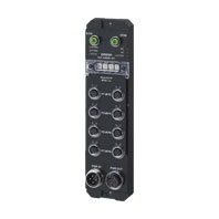
NXR-ILM08C-EIT

Environment-resistive Remote Terminal NXR-series IO-Link Master Unit for EtherNet/IP™

NXR-ILM08C-EIT

Streamline commissioning and maintenance of production equipment. Simple, easy, and quick - Reduce Availability Loss and Quality Loss!

General Specifications

Item Specification
Degree of protection IP67
Operating
environment
Ambient operating temperature -10 to 55°C
Ambient operating humidity 25% to 85% (with no condensation)
Ambient operating atmosphere Must be free from corrosive gases.
Storage temperature -25 to 65°C
Storage humidity 25% to 85% (with no condensation)
Altitude 2,000 m max.
Pollution degree 3 or less: Conforms to IEC 61010-2-201.
Noise immunity 2 kV on power supply line (Conforms to IEC 61000-4-4.)
Overvoltage category Category II: Conforms to IEC 61010-2-201.
EMC immunity level Zone B
Vibration resistance 10 to 60 Hz with amplitude of 0.35 mm, 60 to 150 Hz and 50 m/s2
for 80 minutes each in X, Y, and Z directions.
Shock resistance 150 m/s2, 3 times each in 6 directions along X, Y, and Z axes
Dielectric strength 600 VAC (between isolated circuits)
Insulation resistance 20 MΩ min. (between isolated circuits)
Applicable standards *1 cULus: Listed (UL61010-2-201)
EU: EN 61131-2, RCM
KC: KC Registration
EAC
IO-Link conformance
EtherNet/IP conformance

*1. Ask your OMRON representative for the most recent applicable standards for each model.

EtherNet/IP Communications Specifications

Item Specification
Communications protocols EtherNet/IP protocol
• Implicit messages (Class1)
• Explicit messages (Class 3, UCMM)
Modulation Baseband
Link speed 10 Mbps or 100 Mbps
Ethernet physical layer 100BASE-TX or 10BASE-T (100BASE-TX is recommended.) *1
Ethernet switch Layer-2 switch
Transmission media Category 5 or higher twisted-pair cable
(Recommended cable: double shielded cable with aluminum tape and
braiding)
Transmission distance 100 m or less (Distance between nodes and between hub and node)
Topology Line, Star, Tree, Ring
Number of connected Units • Line, Star
No restrictions
• Tree
There is no restrictions in the number of cascade connections when an
Ethernet switch is used.
• Ring
Dependent on the ring supervisor specifications.
EtherNet/IP
tag data
links
Number of connections 5 *2
Packet interval (RPI) 1 to 10,000 ms
Allowed communications
bandwidth per Unit
4,000 pps
Explicit
messages
Class 3 (number of
connections)
5 *2
However, the maximum number of connections per originator is 2
UCMM (unconnected) Supported *2
EtherNet/IP I/O connection size Input: 296 bytes max. (including input data, status, and unused areas)
Output: 258 bytes max. (including output data and unused areas)
Support
functions
Supported services Tag data link, CIP message communications, automatic clock adjustment
(NTP/SNTP client), BOOTP client, DHCP client
IP address duplication
detection
Provided
Run/Idle header Supported *3
QuickConnect Supported
DLR Ring nodes supported

*1. If tag data links are used, use 100BASE-TX.
*2. The maximum number of connections is 10 when tag data links (Class 1), Class 3, and UCMM are used simultaneously.
*3. You can configure output retention, clear, and other settings during Idle. Refer to the NXR-series IO-Link Master Unit for
     EtherNet/IP™ User’s Manual (Cat.No.W619) for details.

Unit Specifications

Item Specification
IO-Link
specifications
IO-Link connector type Class A
Communications protocol IO-Link protocol
Number of ports 8
Baud rate COM1: 4.8 kbps
COM2: 38.4 kbps
COM3: 230.4 kbps
Topology 1:1
Compliant standards • IO-Link Interface and System Specification Version1.1.2 *1
• IO-Link Test Specification Version1.1.2
Cable specifications • Cable type: Unshielded
• Cable length: 20 m max.
• Electrostatic capacity between lines: 3 nF max.
• Loop resistance: 6 Ω max.
Unit/input power supply voltage 24 VDC (20.4 to 26.4 VDC)
Output power supply voltage 24 VDC (20.4 to 26.4 VDC)
Maximum power supply current 9 A
Sum of Unit/input power supply current and output power supply current
Number of connected Units when
supplying power with through-wiring
No restrictions if power supply specifications are met.
Mounting method Mounting with M5 screws
Mounting strength 100 N
Installation orientation and restrictions Installation orientation: 6 possible orientations
Restrictions: No restrictions
Connector types • EtherNet/IP communications connectors: M12 (D-coding, female) × 2
• Power supply connectors: 7/8 inch (male) × 1, 7/8 inch (female) × 1
• I/O connectors: M12 (A-coding, female) × 8
Connector strength 30 N
Applicable to all connectors
Screw tightening torque • EtherNet/IP communications connectors and I/O connectors
(M12 screw): 0.5 to 0.6 N·m
• Power supply connectors (7/8 inch screw): 1.5 to 1.7 N·m
• Unit mounting (M5 screw): 1.47 to 1.96 N·m
• Rotary switch cover (M3 screw): 0.4 to 0.6 N·m
• Waterproof covers for EtherNet/IP communications connectors
(M12 screw): 0.5 to 0.6 N·m
• Waterproof covers for power supply connectors
(7/8 inch screw): 1.5 to 1.7 N·m
Maximum port current 4 A/port
Total available current between pin 1 and pin 4
Device power
supply *2 in
IO-Link Mode
or SIO (DI)
Mode
Power supply used Unit/input power supply
Rated voltage 24 VDC (20.4 to 26.4 VDC)
Maximum load current 2 A/pin
Short-circuit protection Provided *3
Short-circuit detection Provided *3
Digital inputs
for pin 4 or
digital inputs
for pin 2
(in SIO (DI)
Mode)
Power supply used Unit/input power supply
Rated voltage 24 VDC (20.4 to 26.4 VDC)
Internal I/O common PNP
Input current • Digital inputs for pin 2: 3.0 mA (at 24 VDC)
• Digital inputs for pin 4: 6.3 mA (at 24 VDC)
ON voltage/ON current • Digital inputs for pin 2: 15 VDC min., 2 mA min.
• Digital inputs for pin 4: 15 VDC min., 3 mA min.
OFF voltage/OFF current 5 VDC max., 1 mA max.
ON/OFF response time 1.0 ms max.
Input filter time No filter, 0.25 ms, 0.5 ms, 1 ms (default), 2 ms, 4 ms, 8 ms, 16 ms,
32 ms, 64 ms, 128 ms, 256 ms
Short-circuit protection Provided *3
Short-circuit detection Provided *3
Digital outputs
for pin 4 or
digital outputs
for pin 2
(in SIO (DO)
Mode)
Power supply used Output power supply
Internal I/O common PNP
Output type Open-drain
Rated voltage 24 VDC (20.4 to 26.4 VDC)
Maximum load current 2 A/pin
Leakage current 0.1 mA max.
Residual voltage 1.5 V max.
ON/OFF response time 1.0 ms max.
Short-circuit protection Provided *4
Short-circuit detection Provided *4
Current
consumption
Unit/input power supply 50 mA
Output power supply 100 mA
Weight 440 g
Dimensions 240 × 24.2 × 62 mm (W × H × D)
(The height is 38 mm when the connectors are included.)
Isolation method No isolation
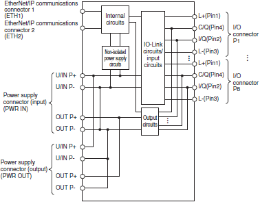
Circuit layout 3794_sp_3_1

*1. IO-Link PREOPERATE is not supported.
*2. Used as a power supply for IO-Link devices or non-IO-Link input devices. Supplies power from the Unit/input power
      supply of the IO-Link Master Unit to external devices through I/O connectors.
*3. Detects a short-circuit that occurred between pin 1 and pin 3 to protect the IO-Link Master Unit.
*4. Detects a short-circuit that occurred between pin 2 and pin 3 and between pin 4 and pin 3 to protect the IO-Link Master
      Unit.

Version Information

The following table shows the relationship between the unit versions of the IO-Link Master Unit and CPU unit, and the corresponding support software versions.

Connecting with NJ/NX CPU Unit

NX-series CPU Unit

IO-Link Master Unit Corresponding versions
Model Unit version CPU unit
version
Sysmac Studio Network
Configurator
CX-ConfiguratorFDT
NXR-ILM08C-EIT Ver.1.1 Ver.1.14 Ver.1.40 Ver.3.69 Ver.2.54
Ver.1.0

NJ-series CPU Unit

IO-Link Master Unit Corresponding versions
Model Unit version CPU unit
version
CJ1W-EIP21 Sysmac Studio Network
Configurator
CX-ConfiguratorFDT
NXR-ILM08C-EIT Ver.1.1 Ver.1.14 Ver.2.1 Ver.1.40 Ver.3.69 Ver.2.54
Ver.1.0

Connecting with CS/CJ/CP CPU Unit

CS1G/CS1H/CJ1M * CPU Unit

* Final order entry date for CJ1M:The end of March, 2021

IO-Link Master Unit Corresponding versions
Model Unit version CPU unit
version
CS1W-EIP21/
CJ1W-EIP21
Network
Configurator
CX-ConfiguratorFDT
NXR-ILM08C-EIT Ver.1.1 Ver.3.0 Ver.2.1 Ver.3.69 Ver.2.54
Ver.1.0

CJ2H-CPU6[]/CJ2M-CPU1[]/CP1H CPU Unit

IO-Link Master Unit Corresponding versions
Model Unit version CPU unit
version
CJ1W-EIP21 Network
Configurator
CX-ConfiguratorFDT
NXR-ILM08C-EIT Ver.1.1 Ver.3.0 Ver.2.1 Ver.3.69 Ver.2.54
Ver.1.0

CJ2H-CPU6[]-EIP CPU Unit

IO-Link Master Unit Corresponding versions
Model Unit version CPU unit
version
CJ1W-EIP21 Network
Configurator
CX-ConfiguratorFDT
NXR-ILM08C-EIT Ver.1.1 Ver.1.5 Ver.2.1 Ver.3.69 Ver.2.54
Ver.1.0

CJ2M-CPU3[] CPU Unit

IO-Link Master Unit Corresponding versions
Model Unit version CPU unit
version
CJ1W-EIP21 Network
Configurator
CX-ConfiguratorFDT
NXR-ILM08C-EIT Ver.1.1 Ver.1.5 Ver.2.1 Ver.3.69 Ver.2.54
Ver.1.0