Page top

61F-LS

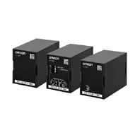
Floatless Level Switch (Compact, Plug-in Type)

61F-LS

Consolidates the Specifications through Free Power Supply, thus Allowing Use in High Temperature Environments with Temperatures of Up to 70°C* * Excluding the DC power supply type.

Specifications

Ratings

61F-LS-CP[]-N
(Normal)
61F-LS-CP[]-S/-A
(High functionality)
61F-LS-CP11-B
(DC power supply)
Controlling materials
and operating
conditions
• For control of ordinary
purified water or sewage
water
• For control of ordinary
purified water or sewage
where operating ambient
temperature is high.
• For control of ordinary
purified water in cases
where the distance
between sewage pumps
and water tanks or
between receiver tanks
and supply tanks is
long or where remote
control is required.
• For control of liquids with
high specific resistance such
as distilled water
• For control of liquids with
low specific resistance such
as salt water, sewage water,
acid chemicals, alkali
chemicals
• When using DC power
• When using battery power,
etc.
Supply
voltage/frequency
100 - 240 VAC 50/60 Hz 100 - 240 VAC 50/60 Hz
24 VAC 50/60 Hz
24 VDC
Operating voltage
range
85% to 110% of rated
voltage
85% to 110% of rated
voltage
85% to 110% of rated
voltage
Operating frequency
range
±5 Hz of the rated frequency ±5 Hz of the rated frequency ±5 Hz of the rated frequency
Power consumption Approx. 3.2 VA max. Approx. 3.2 VA max. Approx. 1 W max.
Contact ratings 5 A at 250 VAC
(Resistive load (cosφ = 1))
1 A at 250 VAC
(Inductive load (cosφ = 0.4))
Minimum applicable load
5 VDC, 1 mA
(reference value)
5 A at 250 VAC
(Resistive load (cosφ = 1))
1 A at 250 VAC
(Inductive load (cosφ = 0.4))
Minimum applicable load
5 VDC, 1 mA
(reference value)
Transistor output
Open collector (NPN)
30 VDC, 100 mA,
leak current 100 μA or less
Relay output (1a)
30 VDC 5 A,
240 VAC 5 A (resistive load)
Minimum applicable load
5 VDC, 10 mA
(reference value)
Ambient temperature -10 to +70°C -10 to +70°C -10 to +55°C
Ambient humidity 25 to 90% RH 25 to 90% RH 25 to 85% RH
Ambient storage
temperature
-10 to +70°C -10 to +70°C -10 to +55°C
Ambient storage
humidity
25 to 90% RH 25 to 90% RH 25 to 85% RH
Weight Approx. 100 g Approx. 100 g Approx. 100 g
Accessories PFC-N8
Wiring distance *1 4 km or less Ultra low-sensitivity,
low-sensitivity,
general-sensitivity: 4 km
High-sensitivity: 50 m
Ultra high-sensitivity: 30 m
100 m or less

*1. Reference values. The wiring distance indicates the values when completely-insulated, 3-core 0.75 mm2, 600-V VCT cables are used.

Characteristics

61F-LS-CP[]-N
(Normal)
61F-LS-CP[]-S/-A
(High functionality)
61F-LS-CP11-B
(DC power supply)
Operation resistance 4 kΩ or more *2 Variable (0 to 100 kΩ)
Operation resistance
error
--- --- Scale 0: 0 to 10 kΩ *3
Scale 100: 100 ± 10 kΩ
Release resistance 15 kΩ or less *2 200% max. of the
operation resistance
Interelectrode voltage 5 VAC 5 VAC 5 VAC
Response time Operate: 80 ms max.
Release: 160 ms max.
*2 Operate: 1.5 s max.
Release: 3.0 s max.
Startup lock time 3 s after turning on the power supply (The LED blinks during the startup lock time)
Insulation resistance *4 100 MΩ min. (at 500 VDC)
Dielectric strength *4 2000 VAC, 50/60 Hz for 1 min.
Life expectancy Electrical:
100,000 operations min.
Mechanical:
5,000,000 operations min.
Electrical:
100,000 operations min.
Mechanical:
5,000,000 operations min.
Relay specification only
Electrical:
70,000 operations min.
Mechanical:
20,000,000 operations min.
Switching between
supply and drainage
--- --- Terminals 7 and 8 open:
Automatic drainage operation
Terminals 7 and 8 shorted:
Automatic supply operation
Approved standards UL61010-1, CAN/CSA C22.2 No.61010-1
CE, RCM
EN61010-1, EN61326-1 Industrial electromagnetic environment

*2. Refer to Dip Switch Settings.
*3. The Detector may not operate around the setting value of “0.” Adjust the sensitivity depending on the actual application.
*4. The insulation resistance and dielectric strength indicate values between power terminals and Electrode terminals, between power terminals and contact terminals, and between Electrode terminals and contact terminals. Refer to Safety Precautions on Catalog.

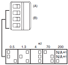
Dip Switch Settings (61F-LS-CP[]-S/-A only)

Symbol Item Specification Notes Factory default
settings
(A) Response
speed
5S
INSTANT (Instantaneous)
(B) Operation
sensitivity
Operation
resistance
Release
resistance
0.5 kΩ or more 2.5 kΩ or less Ultra low-sensitivity
1.3 kΩ or more 4 kΩ or less Low-sensitivity
4 kΩ or more 15 kΩ or less General-purpose
70 kΩ or more 300 kΩ or less High-sensitivity
200 kΩ or more 500 kΩ or less Ultra high-sensitivity

61F-LS Specifications 6

*1. N/A indicates that the switch operates whether it is set ON or OFF.
*2. “0.5, 1.3, 4, 70, 200” indicate the values of operation resistance.