| Item | Rated current (mA) | Coil resistance (Ω) | Max. voltage (V) | Power consumption (mW) |
|---|---|---|---|---|
| Rated voltage | ||||
| 12 VDC | 30 | 400 | 110% | Approx. 360 |
| 18 VDC | 20 | 900 | ||
| 21 VDC | 17.1 | 1,225 | ||
| 24 VDC | 15 | 1,600 | ||
| 48 VDC | 7.5 | 6,400 | ||
| 110 VDC | 3.8 | 28,810 | Approx. 420 |
Relays with Forcibly Guided Contacts

last update: February 16, 2026
| Item | Rated current (mA) | Coil resistance (Ω) | Max. voltage (V) | Power consumption (mW) |
|---|---|---|---|---|
| Rated voltage | ||||
| 12 VDC | 30 | 400 | 110% | Approx. 360 |
| 18 VDC | 20 | 900 | ||
| 21 VDC | 17.1 | 1,225 | ||
| 24 VDC | 15 | 1,600 | ||
| 48 VDC | 7.5 | 6,400 | ||
| 110 VDC | 3.8 | 28,810 | Approx. 420 |
| Item | Rated current (mA) | Coil resistance (Ω) | Max. voltage (V) | Power consumption (mW) |
|---|---|---|---|---|
| Rated voltage | ||||
| 12 VDC | 41.7 | 288 | 110% | Approx. 500 |
| 18 VDC | 27.8 | 648 | ||
| 21 VDC | 23.8 | 882 | ||
| 24 VDC | 20.8 | 1,152 | ||
| 48 VDC | 10.4 | 4,606 | ||
| 110 VDC | 5.3 | 20,862 | Approx. 580 |
Note: 1. The rated current and coil resistance are measured at a coil temperature of 23°C with tolerances of ±15%.
2. The maximum voltage is based on an ambient operating temperature of 23°C maximum.
| Load | Resistive load | Inductive load
(cosφ=0.3, L/R=48 ms) |
|---|---|---|
| Rated load | 250 VAC 6 A
30 VDC 6 A |
AC15 240 VAC 2 A
DC13 24 VDC 1 A 48 VDC 0.5 A 110 VDC 0.2 A |
| Rated carry current | 6 A | |
| Max. switching voltage | 250 VAC, 125 VDC | |
| Max. switching current | 6 A | |
| Contact materials | Au plating + Ag alloy | |
| Contact resistance *1 | 100 mΩ max. | |
|---|---|---|
| Operating time *2 | 20 ms max. | |
| Response time *3 | 10 ms max. | |
| Release time *2 | 20 ms max. | |
| Must operate voltage | 75% max. | |
| Must release voltage | 10% min. | |
| Maximum
operating frequency |
Mechanical | 36,000 operations/h |
| Rated load | 1,800 operations/h | |
| Insulation resistance *4 | 1,000 MΩ min. | |
| Dielectric
Strength *5 *6 |
Between coil
and contacts |
4,000 VAC, 50/60 Hz for 1 min. |
| Between
contacts of different olarity |
4,000 VAC, 50/60 Hz for 1 min. (except for followings)
4 poles (for poles 3-4 in 4-pole Relays), 6 poles (for poles 3-5, 4-6, and 5-6 in 6-pole Relays): 2,500 VAC, 50/60 Hz for 1 min. |
|
| Between
contacts of the same polarity |
1,500 VAC, 50/60 Hz for 1 min. | |
| Vibration resistance | 10 to 55 to 10 Hz, 0.75-mm single amplitude (1.5-mm double amplitude) | |
| Shock
resistance |
Destruction | 1,000 m/s2 |
| Malfunction | 100 m/s2 | |
| Durability
*7 |
Mechanical | 10,000,000 operations min. (at approx. 36,000 operations/h) |
| Electrical | 100,000 operations min. (at the rated load) | |
| Failure rate (P level)
(reference value *8) |
5 VDC, 1 mA | |
| Ambient operating
temperature *9 |
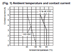
12 to 48 VDC: -40 to 85°C (with no icing or condensation)
110 VDC: -40 to 60°C (with no icing or condensation) |
|
| Ambient operating humidity | 5% to 85% | |
| Weight | 4 poles: Approx. 22 g
6 poles: Approx. 25 g |
|
Note: 1. The above values are initial values.
2. Performance characteristics are based on coil temparature of 23°C.
*1. The contact resistance was measured with 1 A at 5 VDC using the voltage-drop method.
*2. These times were measured at the rated voltage and an ambient temperature of 23°C. Contact bounce time is not
included.
*3. The response time is the time it takes for the normally open contacts to open after the coil voltage is turned OFF.
Contact bounce time is included. Measurement conditions: Rated voltage operation, Ambient temperature: 23°C
*4. The insulation resistance was measured with a 500-VDC megohmmeter at the same locations as the dielectric
strength was measured.
*5. Pole 3 refers to terminals 31-32 or 33-34, pole 4 refers to terminals 43-44, pole 5 refers to terminals 53-54, and
pole 6 refers to terminals 63-64.
*6.When using a P7SA Socket, the dielectric strength between coil contacts/between contacts of different polarity is 2,500
VAC, 50/60 Hz for 1 min.
*7. The durability is for an ambient temperature of 15 to 35°C and an ambient humidity of 25% to 75%.
*8. The failure rate is based on an operating frequency of 300 operations/min.
*9. 12 to 48 VDC: When operating between 70 and 85°C, reduce the rated carry current of 6 A by 0.1 A for each degree above 70°C. (See Fig. 1.)
110 VDC: When operating between 45 and 60°C, reduce the rated carry current of 6 A by 0.27 A for each degree above 45°C. (See Fig. 1.)

| Model | Push-In Plus terminals | Screw terminals | PCB terminals | ||||
|---|---|---|---|---|---|---|---|
| 4 poles | 6 poles | 4 poles | 6 poles | 4 poles | 6 poles | ||
| P7SA-10F-ND-PU | P7SA-14F-ND-PU | P7SA-10F(-ND) | P7SA-14F(-ND) | P7SA-10P | P7SA-14P | ||
| Ambient operating temperature | P7SA-[]F-ND(-PU): -20 to +70°C
P7SA-[]F: -40 to +85°C (with no icing or condensation) |
-40 to +85°C
(with no icing or condensation) |
|||||
| Ambient operating humidity | 25% to 85% | 5% to 85% | |||||
| Continuous carry current | 6 A *1 | ||||||
| Dielectric
strength |
Between coil
and contact terminals |
4,000 VAC for 1 min. | 2,500 VAC for 1 min. | ||||
| Between contact
terminals of different polarity |
2,500 VAC for 1 min. | ||||||
| Between contact
terminals of same polarity |
1,500 VAC for 1 min. | ||||||
| Insulation resistance | 1,000 MΩ min. *2 | ||||||
| Weight | Approx. 58 g | Approx. 70 g | Approx. 44 g | Approx. 59 g | Approx. 9 g | Approx. 10 g | |
*1. When operating the P7SA-[]F-ND-PU at a temperature between 50 and 70°C, reduce the continuous current
(6 A at 50°C or less) by 0.25 A for each degree above 50°C.
When operating the P7SA-[]F-ND at a temperature between 50 and 70°C, reduce the continuous current
(6 A at 50°C or less) by 0.3 A for each degree above 50°C.
When operating the P7SA-[]F at a temperature between 50 and 85°C, reduce the continuous current
(6 A at 50°C or less) by 0.1 A for each degree above 50°C.
*2. Measurement conditions: For 500 VDC applied to the same location as for dielectric strength measurement.
| Application | Applicable
sockets |
Models | Maximum
carry current |
Ambient operating
temperature |
Ambient operating
humidity |
|---|---|---|---|---|---|
| Crossover wiring of
contact terminals (bottom) |
P7SA-[]F-ND-PU | XW5S-P2.5-2[] | 24 A | -40 to 55°C | 5% to 95% |
| XW5S-P2.5-3[] | |||||
| XW5S-P2.5-4[] | |||||
| XW5S-P2.5-5[] |
| Models | Operating
Coil Ratings |
Standard number | Certification No. | Contact ratings |
|---|---|---|---|---|
| G7SA-2A2B
G7SA-3A1B G7SA-3A3B G7SA-4A2B G7SA-5A1B |
12, 18, 21,
24, 48, 110 VDC |
EN/IEC 61810-1
Electromagnetic relay EN 61810-3 Relays with forcibly guided contacts |
125547 | 250 VAC 6 A (Resistive load)
30 VDC 6 A (Resistive load) |
| EN/IEC 60947-5-1 | AC15 240 VAC 2 A
(Resistive load) DC13 24 VDC 1 A (Resistive load) 48 VDC 0.5 A 110 VDC 0.2 A |
| Models | Category | Listed/Recognized | Contact ratings | Operating Coil ratings |
|---|---|---|---|---|
| G7SA-2A2B | E41515 | Recognized | 6 A, 250 VAC (Resistive)
6 A, 30 VDC (Resistive) |
12, 18, 21, 24, 48, 110 VDC |
| G7SA-3A1B | ||||
| G7SA-3A3B | ||||
| G7SA-4A2B | ||||
| G7SA-5A1B |
| Models | Class number | File No. | Contact ratings | Operating Coil ratings |
|---|---|---|---|---|
| G7SA-2A2B | 3211-07 | LR35535 | 6 A, 250 VAC (Resistive)
6 A, 30 VDC (Resistive) |
12, 18, 21, 24, 48, 110 VDC |
| G7SA-3A1B | ||||
| G7SA-3A3B | ||||
| G7SA-4A2B | ||||
| G7SA-5A1B |
| Models | Applicable standard number |
|---|---|
| G7SA-2A2B DC24 | KS C IEC 61810-1 |
| G7SA-3A1B DC24 | |
| G7SA-3A3B DC24 | |
| G7SA-4A2B DC24 | |
| G7SA-5A1B DC24 |
| Models | Standard number | Certification No. |
|---|---|---|
| G7SA | GB/T, 21711.1 | CQC14002119869 |
| Models | EMC Directive | Low Voltage Directive | Machinery Directive |
|---|---|---|---|
| P7SA (Excluding -P type) | Not applicable | Applicable | Not applicable |
| P7SA-PU | Not applicable | Applicable | Not applicable |
The CE compliance declaration was made in combination with the Safety Relay.
| Models | Ratings | Standard number | Certification No. |
|---|---|---|---|
| P7SA | --- | EN61984 | 40007586 |
| Models | Ratings | Standard number | Certification No. |
|---|---|---|---|
| P7SA-PU | --- | EN61984 | R50356981 |
| Models | Category | Listed/Recognized |
|---|---|---|
| P7SA | SWIV2 | Recognized |
| P7SA-PU | SWIV2, SWIV8 | Recognized |
| Models | Class number | File No. |
|---|---|---|
| P7SA | 3211-07, 3211-87 | LR35535 |
| P7SA-PU | 3211-07, 3211-87 | LR35535 |
last update: February 16, 2026