Question
Does the input current change for Solid-state Relays with a wide rated input voltage?
Answer
In Solid-state Relays which have wide input voltages (such as G3F and G3H), the input impedance depends on the input voltage and changes in the input current. For semiconductor-driven Solid-state Relays, changes in voltage can cause malfunctions in the semiconductor, so be sure to check the actual device before usage.
This is not the case for Solid-state Relays with DC inputs that use a constant current input method (such as G3NA and G3PA).
Ratings
| Applicable model | Item | Rated voltage | Operating voltage | Impedance | |
| Model | |||||
| ○ | G3H-203SN | 5 to 24 VDC | 4 to 28 VDC | 1.5 kΩ +20%, -10% * | |
| G3H-203SLN | DC | 5 V | 4 to 6 VDC | 390 Ω ±20% | |
| 12 V | 9.6 to 14.4 VDC | 900 Ω ±20% | |||
| 24 V | 19.2 to 28.8 VDC | 2 kΩ ±20% | |||
| ○ | G3HD-X03SN | 5 to 24 VDC | 4 to 28 VDC | 1.5 kΩ +20%, -10% * | |
| ○ | G3H-203S | 4 to 24 VDC | 3 to 28 VDC | 1.5 kΩ +20%, -10% * | |
| G3H-203SL | DC | 5 V | 4 to 6 VDC | 390 Ω ±20% | |
| 12 V | 9.6 to 14.4 VDC | 900 Ω ±20% | |||
| 24 V | 19.2 to 28.8 VDC | 2 kΩ ±20% | |||
| ○ | G3HD-X03S | 4 to 24 VDC | 3 to 28 VDC | 1.5 kΩ +20%, -10% * | |
Note:The input impedance is measured at the maximum operating voltage.
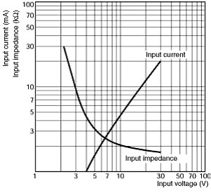
Applicable Input Impedance for a Photocoupler-type Solid-state Relays without Indicators (Typical Example)
G3F or G3H (No Indicators)
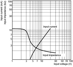
Applicable Input Impedance for a Photocoupler-type Solid-state Relays with Indicators (Typical Example)
G3B, G3F, or G3H (with Indicators)
Recommended Products
 MY
MY
Best-selling, general-purpose relays that can be selected based on operating environment and application
LY
Power-switching Compact General-purpose Relays
G3PE (Three-phase)
Compact, Slim-profile SSRs with Heat Sinks. Solid State Contactors for Three-phase Heaters Reduced Installation Work with DIN Track Mounting.