Question
How are the internal Solid-state Relays circuits configured?
Answer
Examples of Solid-state Relays Internal Circuit Configuration
Load specifications
AC load
| Zero cross function | Isolation | Circuit configuration | Model |
| Yes (See note 1.) | Photo- coupler | 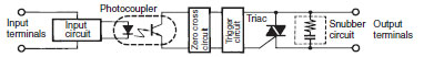 | G3H G3B G3F G3NA (AC input) |
| No | Phototriac | 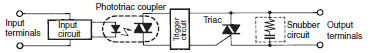 | G3NE G3J G3F G3H G3TA-OA |
| Yes (See note 1.) | Phototriac | 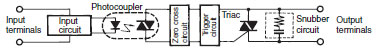 | G3PA-VD G3PB (single phase) G3NA (DC input) G3NE |
| Yes (See note 1.) | Phototriac | 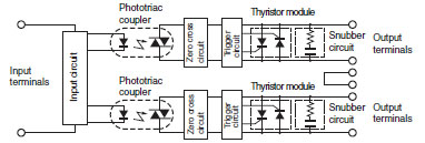 | G3PB-2(N) (three phases) (See note 2.) |
| Yes (See note 1.) | Phototriac | 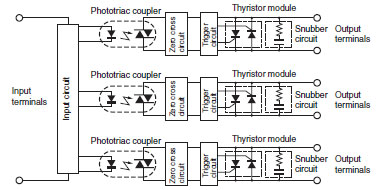 | G3PB-3(N) (three phases) (See note 2.) |
| Yes (See note 1.) | Photo- coupler | 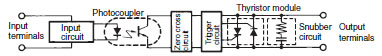 | G3NA-4[][]B G3NH G3PA-4[][]B G3PB-5[][]B |
Load specifications
DC load
| Zero cross function | Isolation | Circuit configuration | Model |
| --- | Photo-coupler | 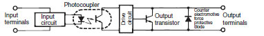 | G3FD, G3HD G3BD G3TA-OD G3NA-D |
Load specifications
AC/DC load
| Zero cross function | Isolation | Circuit configuration | Model |
| No | Photo-diode coupler | 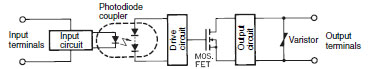 | G3FM |
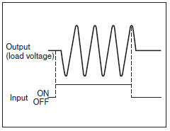
Note 1:
The zero cross function turns ON the Solid-state Relay when the AC load voltage is 0 V or close to 0 V. Solid-state Relays with the zero cross function are effective in the following ways.
・Clicking noise when a load is turned ON is reduced.
・Effects on the power supply are reduced by suppressing inrush current with loads, such as lamps, heaters, and motors, thereby reducing inrush current protection circuits.
Note 2:
For 200-V models, use a triac on the output switching elements.
Recommended Products
 MY
MY
Best-selling, general-purpose relays that can be selected based on operating environment and application
LY
Power-switching Compact General-purpose Relays
G3PE (Three-phase)
Compact, Slim-profile SSRs with Heat Sinks. Solid State Contactors for Three-phase Heaters Reduced Installation Work with DIN Track Mounting.